

 Manufacturers
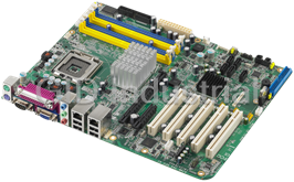
ADVANTECH PCA-6149

Description
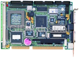
Full-size 486 PCI/ISA-bus CPU card with SVGA interface
Part Number
PCA-6149
Price
Request Quote
Manufacturer
ADVANTECH
Lead Time
Request Quote
Category
Single Board Computers
Specifications
System Chipset
SIS 496/497
Video Chipset
Qualcomm Snapdragon 600
Form Factor
PICMG 1.0
BIOS
AWARD
Board Size
13.3" (L) x 4.8" (W) (338.5 mm x 122 mm)
Board Weight
1.2 lbs (0.5 Kg)
Bus Interface
ISA and PCI (PC/AT) bus
Bus Speed
8 MHz (ISA), CPU clock or ½ CPU clock speed (PCI)
Cache Memory
8 KB on-chip and 256/512 KB 2nd level
Chipset
SIS 496/497
CMOS Backup
CMOS data backup in EEPROM, avoiding data loss
CPU
80486SX/DX/DX2/DX4-25/33/40/50/66/75/100 MHz, or P24T Pentium Overdrive Processor
Data Bus
32 bit
Display Controller
SVGA, PCI bus, ET4000/W32P chipset with 1 MB standard video memory, upgradable to 2 MB. Provides 32-bit graphic throughput with Windows acceleration. Supports resolutions up to 1280 x 1024 in 16 colors, 1024 x 768 in 65536 colors, or 800 x 600 in 16.8 million colors.
Enhanced Bidirectional Parallel Port
Configurable to LPT1, LPT2, LPT3, or disabled. Standard DB-25 female connector provided. Supports SPP/EPP/ECP
Enhanced IDE Hard Disk Drive Interface
Fast VL bus. Supports up to four IDE (AT bus) large (up to 8 GB) hard disk drives or other enhanced IDE devices. Supports mode 3 (11.1 MB/sec. data transfer rate). BIOS enabled/disabled
Floppy Disk Drive Interface
Supports up to two floppy disk drives, 5.25" (360 KB and 1.2 MB) and/or 3.5" (720 KB, 1.44 MB and 2.88MB). BIOS enabled/disabled
Keyboard/PS/2 Mouse Connector
A 6-pin mini DIN keyboard connector is located on the mounting bracket for easy connection of a keyboard and/or a PS/2 mouse (selected by jumper). An on-board keyboard 5-pin header connector is also available
Max Power Requirements
+5 V @ 3.5 A
Operating Temp
32o to 140o F (0° to 60° C)
Power Supply Voltage
+5 V (4.75 V to 5.25 V), +12 V, -12 V
Processing
32 bit
RAM Memory
1 MB to 256 MB. Uses four 72-pin SIMM sockets, 72-pin sockets accept 1, 2, 4, 8, 16, 32 or 64 MB SIMMs
Real Time Clock/Calendar
Dallas DS-12887 with lithium battery backup for 10 years of data retention
Serial Ports
Two serial RS-232 ports, both with 16C550 UARTs (or compatible) with 16-byte FIFO buffer. Support speeds up to 115Kbps. Ports can be individually configured as COM1, COM2 or disabled.
Shadow RAM Memory
Supports system and video BIOS of up to 256 KB in 32 KB blocks
Storage Temp
-40o to 176o F (-40° to 80° C)
System Performance (with 80486DX4-100 MHz CPU)
363 MHz, Landmark speed V2.0
WatchDog Timer
Can generate a system reset or IRQ11. BIOS enabled/disabled. The timer interval is 0.5 ~ 1008 sec. (12 levels), and is also set in the BIOS.
Features
- A 6-pin mini DIN keyboard connector is located on the mounting bracket for easy connection of a keyboard and/or a PS/2 mouse (selected by jumper).
- An on-board keyboard 5-pin header connector is also available.
- CMOS data backup in EEPROM.
- Supports system and video BIOS of up to 256 KB in 32 KB blocks.
- Two serial RS-232 ports, both with 16C550 UARTs (or compatible) with 16-byte FIFO buffer.
Datasheet

Extracted Text
PCA-6149
Full-size 486 PCI/ISA-bus CPU card
with SVGA interface
User's Manual
Copyright Notice
This document is copyrighted, 1996, by Advantech Co., Ltd. All rights
are reserved. Advantech Co., Ltd., reserves the right to make improve-
ments to the products described in this manual at any time without
notice.
No part of this manual may be reproduced, copied, translated, or
transmitted in any form or by any means without the prior written
permission of Advantech Co., Ltd. Information provided in this manual
is intended to be accurate and reliable. However, Advantech Co., Ltd.
assumes no responsibility for its use, nor for any infringements upon
the rights of third parties which may result from its use.
Acknowledgements
AMD is a trademark of Advanced Micro Devices, Inc.
AMI is a trademark of American Megatrends Inc.
IBM, PC AT and VGA are trademarks of International Business
Machines Corporation.
MS-DOS is a trademark of Microsoft Corporation.
SMC is a trademark of Standard Microsystems Corporation
SiS is a trademark of Silicon Integrated Systems Corporation.
ET4000/W32P is a trademark of Tseng Labs., Inc. (USA).
Part No. 2006149020 3rd Edition
Printed in Taiwan May 1996
A Message to the Customer....
Advantech Customer Services
Each and every Advantech product is built to the most exacting
specifications to ensure reliable performance in the unusual and
demanding conditions typical of industrial environments. Whether
your new Advantech equipment is destined for the laboratory or the
factory floor, you can be assured that it will provide the reliability and
ease of operation for which the name Advantech has come to be
known.
Your satisfaction is our number one concern. Here is a guide to
Advantech’s customer services. To ensure you get the full benefit of
our services, please follow the instructions below carefully.
Technical Support
We want you to get the maximum performance from your products. If
you run into technical difficulties, we are here to help. But please
consult this manual first.
If you still can’t find the answer, gather all the information or questions
that apply to your problem and, with the product close at hand, call
your dealer. Our dealers are trained and ready to give you the support
you need to get the most from your Advantech products. In fact, most
problems reported are minor and are able to be easily solved over the
phone.
In addition, free technical support is available from Advantech
engineers every business day. We are always ready to give advice on
application requirements or specific information on the installation and
operation of any of our products.
Product warranty
Advantech warrants to you, the original purchaser, that each of its
products will be free from defects in materials and workmanship for
one year from the date of purchase.
This warranty does not apply to any products which have been
repaired or altered by other than repair personnel authorized by
Advantech, or which have been subject to misuse, abuse, accident or
improper installation. Advantech assumes no liability as a conse-
quence of such events under the terms of this Warranty.
Because of Advantech’s high quality-control standards and rigorous
testing, most of our customers never need to use our repair and
replacement service. If an Advantech product ever does prove
defective, it will be repaired at no charge during the warranty period.
For out-of-warranty repairs, you will be billed according to the cost of
replacement materials, service time and freight. Please consult your
dealer for more details.
If you think you have a defective product, follow these steps:
1. Collect all the information about the problem encountered (e.g. type
of PC, CPU speed, Advantech products used, other hardware and
software used etc.). Note anything abnormal and list any on-screen
messages you get when the problem occurs.
2. Call your dealer and describe the problem. Please have your
manual, product and any other information readily available.
3. If your product is diagnosed as defective, obtain an RMA (return
material authorization) number from your dealer. This allows us to
process your return more quickly.
4. Carefully pack the defective product, a completely filled-out Repair
and Replacement Order Card and a photocopy of a dated proof of
purchase (such as your sales receipt) in a shippable container. A
product returned without dated proof of purchase is not eligible for
warranty service.
5. Write the RMA number visibly on the outside of the package and
ship it prepaid to your dealer.
Packing list
Before you begin installing your card, please make sure that the
following materials have been shipped:
1 PCA-6149 CPU card
1 6-pin mini-DIN keyboard and PS/2 mouse adapter
1 Hard disk drive (IDE) interface cable (40 pin)
1 Floppy disk drive interface cable (34 pin)
1 Parallel port adapter (26 pin) and COM2 adapter (9 pin) kit
2 Utility disks with SVGA utility programs and drivers
If any of these items are missing or damaged, contact your distributor
or sales representative immediately.
Contents
Chapter 1 Hardware Configuration .................................................1
Introduction ................................................................................ 2
Specifications .............................................................................. 3
System ............................................................................................3
I/O ..................................................................................................3
Industrial features ...........................................................................4
General ...........................................................................................4
Board layout ................................................................................ 5
Jumpers and connectors ........................................................... 6
Safety precautions ...................................................................... 7
Jumper settings .......................................................................... 8
How to set jumpers ........................................................................8
CPU type select (JP1, 2, 5, 6, 12~20, 22~25, 27) ...........................9
CPU clock select (JP27)..............................................................10
CPU clock delay time select (JP25) ............................................ 10
PCI bus clock setting (JP24) ........................................................ 11
P24D WB/WT select (JP1) and P24T WB/WT select (JP21) ...12
Cache memory size select (JP4) ..................................................12
Parallel port ECP/EPP DMA channel (JP28) .............................13
Watchdog timer – system reset/IRQ11 (JP31) ............................13
Keyboard or PS/2 mouse select (JP36, JP37) .............................13
Installing DRAM (SIMMs) .................................................... 14
Chapter 2 Connecting Peripherals ................................................ 15
Enhanced IDE connectors (CN1, CN2)................................ 17
Floppy drive connector (CN3) ............................................... 18
Parallel port (CN4)................................................................... 18
Keyboard and PS/2 mouse connectors (J7, J9) .................. 19
External switches and indicators ........................................... 20
Power LED and keylock (JP7) ....................................................20
External speaker (JP8).................................................................20
Turbo LED (JP9) ......................................................................... 21
Reset switch (JP10) .....................................................................21
Turbo switch (JP11) ..................................................................... 21
Hard disk drive LED (JP30) ........................................................ 21
Display connectors ................................................................... 22
VGA connector (J8).....................................................................22
Feature connector (CN5) .............................................................22
Cooling fan power connector (J1) ......................................... 23
Serial ports ................................................................................ 23
RS-232 connections (COM1, COM2).......................................... 24
Chapter 3 AWARD BIOS Setup ...................................................... 25
AWARD BIOS Setup ............................................................... 26
Entering setup ............................................................................... 26
Standard CMOS setup ................................................................. 27
BIOS features setup.....................................................................28
CHIPSET features setup .............................................................32
Power management setup ............................................................33
PCI slot configuration ................................................................... 36
Load BIOS defaults ..................................................................... 38
Load setup defaults ...................................................................... 38
Password setting ..........................................................................38
IDE HDD auto detection .............................................................38
Save & Exit setup ........................................................................ 38
Exit without saving ....................................................................... 38
Chapter 4 PCI VGA Setup .............................................................. 39
Before you begin ...................................................................... 40
Installation ................................................................................. 41
Appendix A Programming the Watchdog Timer ......................... 43
Programming the watchdog timer ......................................... 44
Appendix B POST LEDs ................................................................. 45
POST LEDs .............................................................................. 47
Appendix C Hardware Interrupt Information ............................... 53
1
Hardware
Configuration
This chapter gives background informa-
tion on the PCA-6149. It then shows you
how to configure the card to match your
application and prepare it for installation
into your PC.
Sections include:
Card specifications
Board layout
Safety precautions
Jumper settings
Installing DRAM (SIMMs)
Chapter 1 Hardware Configuration 1
CHAPTER
Introduction
The PCA-6149 is an all-in-one single board 486 computer that includes an
on-board SVGA controller with PCI bus and ISA bus support. It packs
all the functions of an industrial computer, including display capabilities,
on a single full-size card. The PCA-6149 is fully PC/AT compatible, so
your software will run without modifications.
The on-board PCI bus SVGA controller uses the ET4000/W32P chipset
with 1 or 2 MB video memory. This chipset, used with the local PCI bus,
enables 32-bit graphic throughput at up to 33 MHz. The ET4000/W32 also
offers Windows graphics acceleration. These features are excellent for
display-intensive applications.
Another feature of the PCA-6149 is the inclusion of a fast VL bus
enhanced IDE controller. This controller supports mode 3, which enables
data transfer rates in excess of 11 MB/second. Up to four IDE devices can
be connected, including large hard disks (up to 8 GB), CD-ROM drives,
Tape backup drives or other enhanced IDE devices.
On-board features also include two high-speed RS-232 serial ports with
16C550 UARTs, one bidirectional SPP/EPP/ECP parallel port and a floppy
drive controller. In addition to the 486's 8 KB of on-chip cache memory,
the PCA-6149 includes an extra 256 KB or 512 KB of second level cache
memory on-board.
If program execution is halted by a program bug or EMI, the board's 12-
level watchdog timer can automatically reset the CPU or generate an
interrupt. This ensures reliability in unmanned or standalone systems. The
timer interval of the watchdog timer is set in the BIOS, eliminating jumper
switch setting.
The PCA-6149 provides four 72-pin SIMM (Single In-line Memory
Module) sockets for its on-board system DRAM. These sockets give you
the flexibility to configure your system from 1 MB to 256 MB of DRAM
using the most economical combination of SIMMs.
The CMOS data of the PCA-6149 is backed up in EEPROM, which avoids
data loss, even when the battery fails.
To make using the DX4-100 easy, the PCA-6149 includes an on-board
DC-to-DC converter that automatically switches to 3.3 V.
2 PCA-6149 User's Manual
Specifications
System
CPU: 80486SX/DX/DX2/DX4-25/33/40/50/66/75/100 MHz, or
P24T Pentium Overdrive Processor
Cache memory size: 8 KB on-chip and 256/512 KB 2nd level
Bus interface: ISA and PCI (PC/AT) bus
Chipset: SIS 496/497
BIOS: AWARD
Display controller: SVGA, PCI bus, ET4000/W32P chipset with 1
MB standard video memory, upgradable to 2 MB. Provides 32-bit
graphic throughput with Windows acceleration. Supports resolu-
tions up to 1280 x 1024 in 16 colors, 1024 x 768 in 65536 colors, or
800 x 600 in 16.8 million colors.
Data bus: 32 bit
Processing ability: 32 bit
Bus speed: 8 MHz (ISA), CPU clock or ½ CPU clock speed (PCI)
RAM memory: 1 MB to 256 MB. Uses four 72-pin SIMM sockets.
72-pin sockets accept 1, 2, 4, 8, 16, 32 or 64 MB SIMMs
Shadow RAM memory: Supports system and video BIOS of up to
256 KB in 32 KB blocks
I/O
Enhanced IDE hard disk drive interface:
Fast VL bus. Supports up to four IDE (AT bus) large (up to 8 GB)
hard disk drives or other enhanced IDE devices. Supports mode 3
(11.1 MB/sec. data transfer rate). BIOS enabled/disabled
Floppy disk drive interface: Supports up to two floppy disk drives,
5.25" (360 KB and 1.2 MB) and/or 3.5" (720 KB, 1.44 MB and 2.88
MB). BIOS enabled/disabled
Chapter 1 Hardware Configuration 3
Enhanced bidirectional parallel port: Configurable to LPT1,
LPT2, LPT3, or disabled. Standard DB-25 female connector
provided. Supports SPP/EPP/ECP
Serial ports: Two serial RS-232 ports, both with 16C550 UARTs (or
compatible) with 16-byte FIFO buffer. Support speeds up to 115
Kbps. Ports can be individually configured as COM1, COM2 or
disabled.
Real time clock/calendar: Dallas DS-12887 with lithium battery
backup for 10 years of data retention
Keyboard/ PS/2 mouse connector: A 6-pin mini DIN keyboard
connector is located on the mounting bracket for easy connection of
a keyboard and/or a PS/2 mouse (selected by jumper). An on-board
keyboard 5-pin header connector is also available.
Industrial features
Watchdog timer: Can generate a system reset or IRQ11. BIOS
enabled/disabled. The timer interval is 0.5 ~ 1008 sec. (12 levels),
and is also set in the BIOS.
CMOS backup: CMOS data backup in EEPROM, avoiding data
loss
General
System performance (with 80486DX4-100 MHz CPU):
363 MHz, Landmark speed V2.0
Max. power requirements: +5 V @ 3.5 A
Power supply voltage:
+5 V (4.75 V to 5.25 V), +12 V, -12 V
o o o o
Operating temperature: 32 to 140 F (0 to 60 C)
o o o o
Storage temperature: -40 to 176 F (-40 to 80 C)
Board size: 13.3" (L) x 4.8" (W) (338.5 mm x 122 mm)
Board weight: 1.2 lbs (0.5 Kg)
4 PCA-6149 User's Manual
Board layout
PCA-6149 PCB Layout
Chapter 1 Hardware Configuration 5
CN1 CN4
1 CN3 1 1
P.O.S.T LEDs +5V GND +12V
J1
1
+
1
1 JP9 1
1
JP11
JP3
JP1
CN2
COM2
J7
JP28 JP29 CN5
JP2
JP8 JP10
JP7
JP14
486 CPU
J8
VGA
JP13
JP12
JP18
JP15
+
JP16JP17
JP24 JP25 JP30
JP31
JP19
JP21JP22
JP4
Display memory
COM1
JP6 JP20
JP36
JP27
JP33
JP5
4 3 2 1
JP37
SIMM
J9
Jumpers and connectors
Connectors on the board link it to external devices such as hard disk
drives, a keyboard, or floppy drives. In addition, the board has a
number of jumpers which you use to configure it for your application.
The table below lists the function of each of the board jumpers and
connectors. Later sections in this chapter give instructions on setting
jumpers and detailed information on each jumper setting. Chapter 2
gives instructions for connecting external devices to your card.
Jumpers and connectors
Number Function
JP1 P24D WB/WT select
JP2 CPU type select
JP3 CPU type select
JP4 Cache size select
JP5 CPU type select
JP6 CPU type select
JP7 Power LED and keylock
JP8 External speaker
JP9 Turbo LED
JP10 Reset switch
JP11 Turbo switch
JP12~JP20 CPU type select
JP21 P24T WB/WT select
JP22 CPU type select
JP23 Factory reserved
JP24 PCI bus clock select
JP25 CPU clock delay time select
JP26 Factory reserved
JP27 CPU bus clock select
JP28 Parallel port ECP/EPP DMA channel
JP29 On-board Super I/O enabled/disabled select
JP30 HDD LED
JP31 Watchdog timer reset/IRQ11 select
6 PCA-6149 User's Manual
Number Function
JP32~35 Factory reserved
JP36 DIN connector keyboard or PS/2 mouse select
JP37 DIN connector keyboard or PS/2 mouse select
CN1 1st enhanced IDE connector
CN2 2nd enhanced IDE connector
CN3 FDD connector
CN4 Parallel connector
CN5 VGA feature connector
J1 Cooling fan power connector
J2 ~J6 Factory reserved
J7 External keyboard connector
J8 VGA connector
J9 Keyboard or PS/2 mouse connector
COM1 Serial port 1
COM2 Serial port 2
Safety precautions
Follow these simple precautions to protect yourself from harm and
your PC from damage.
1. To avoid electric shock, always disconnect the power from your PC
chassis before you work on it. Don’t touch any components on the
CPU card or other cards while the PC is on.
2. Disconnect power before making any configuration changes. The
sudden rush of power as you connect a jumper or install a card
may damage sensitive electronic components.
3. Always ground yourself to remove any static charge before you
touch your CPU card. Be particularly careful not to touch the chip
connectors. Modern integrated electronic devices, especially CPUs
and memory chips, are extremely sensitive to static electric
discharges and fields. Keep the card in its antistatic packaging
when it is not installed in the PC, and place it on a static dissipative
mat when you are working with it. Wear a grounding wrist strap
for continuous protection.
Chapter 1 Hardware Configuration 7
Jumper settings
This section tells how to set the jumpers to configure your card. It
gives the card default configuration and your options for each jumper.
After you set the jumpers and install the card, you will also need to
run the BIOS Setup program (discussed in Chapter 3) to configure the
serial port addresses, floppy/hard disk drive types and system operat-
ing parameters. Connections, such as hard disk cables, appear in
Chapter 2.
For the locations of each jumper, see the board layout diagram
depicted earlier in this chapter.
How to set jumpers
You configure your card to match the needs of your application by
setting jumpers. A jumper is the simplest kind of electric switch. It
consists of two metal pins and a small metal clip (often protected by a
plastic cover) that slides over the pins to connect them. To “close” a
jumper you connect the pins with the clip. To “open” a jumper you
remove the clip. Sometimes a jumper will have three pins, labeled 1, 2
and 3. In this case you connect either pins 1 and 2 or 2 and 3.
3
2
1
Open Open Open Open Open Closed Closed Closed Closed Closed Closed 2-3 Closed 2-3 Closed 2-3 Closed 2-3 Closed 2-3
You may find pair of needle-nose pliers useful for setting the jumpers.
If you have any doubts about the best hardware configuration for your
application, contact your local distributor or sales representative
before you make any changes.
8 PCA-6149 User's Manual
CPU type select (JP1, 2, 5, 6, 12~20, 22~25, 27)
In order for the system to function properly, the jumpers must be set to
accommodate the CPU installed on the CPU card.
CPU type select (JP2, 5, 6, 12~20, 22)
CPU \ JP 1 2 5 6 12 13 14 15 16 17 18 19 20 22 23 24 25 27
Intel
SX-33
Intel
DX-33
DX2-66
Intel
DX4-100
Cyrix
DX2-66;
SGS
DX2-66
Cyrix
DX2-80
(5V)
Cyrix
DX2-80
(3.45V)
AMD
DX4-100
(standard &
enhanced)
AMD
DX4-120
Chapter 1 Hardware Configuration 9
CPU \ JP 1 2 5 6 12 13 14 15 16 17 18 19 20 22 23 24 25 27
AMD
5x86-133
Intel
DX4-75;
P24D
CPU clock select (JP27)
The user can choose the CPU frequency by setting the clock generator
jumper JP27. If you change processor in the future, you must make
sure that the jumpers are configured for the correct CPU clock speed.
Do this before installing and applying power to the CPU board.
CPU bus clock
25MHz 33MHz 40MHz
JP27
CPU clock delay time select (JP25)
For better system reliability, enable the CPU clock delay time select
(JP25) for CPUs with an external clock faster than 33 MHz (i.e.
486DX-40).
CPU clock delay time select (JP25)
Delay disabled Delay enabled
JP25
10 PCA-6149 User's Manual
PCI bus clock setting (JP24)
The PCI clock speed can be synchronized with either the CPU clock
speed or one-half the CPU clock speed to accommodate older
software. JP24 controls the PCI clock.
PCI bus clock setting (JP24)
CPU clock ½ CPU clock
JP24
The following table lists some CPU types and their respective CPU
clocks:
CPU type CPU clock
486DX/SX-33 33 MHz
486DX-40 40 MHz
486DX2-50 25 MHz
486DX2-66 33 MHz
486DX4-75 25 MHz
486DX4-100 33 MHz
Note: If the CPU external clock is faster than 33 MHz, set
the PCI clock to ½ CPU clock.
Chapter 1 Hardware Configuration 11
P24D WB/WT select (JP1) and
P24T WB/WT select (JP21)
The P24D and P24T Pentium OverDrive processors include write-
back or write-through on-chip cache memory that can be selected
using JP1 and JP21, respectively.
P24D WB/WT select (JP1) and P24T WB/WT select (JP21)
P24D (JP1) P24T (JP21)
1 1
Write-back
2 2
3 3
1
1
Write-through
2 2
3 3
Note: For AMD DX/DX2 CPUs, close pins 2 and 3 on JP1. For
all other CPU types, simply leave JP1 and JP21 open.
Cache memory size select (JP4)
When you upgrade the cache memory on the PCA-6149 to 512 KB,
you will need to set JP4 as follows:
Cache memory size select (JP4)
256 KB (default) 512 KB
JP4
12 PCA-6149 User's Manual
Parallel port ECP/EPP DMA channel (JP28)
You can set the DMA channel of the parallel port to either DMA 1 or
DMA 3.
Parallel port ECP/EPP DMA channel (JP28)
DMA 1 (default) DMA 3
JP28
Watchdog timer – system reset/IRQ11 (JP31)
When the watchdog timer activates (CPU processing has come to a
halt), it can reset the system or generate an interrupt on IRQ11. Set
JP31 as shown below:
Watchdog timer system reset/IRQ11 select (JP31)
Reset (default) IRQ11
2 4
2 4
1 3
1 3
JP31
Keyboard or PS/2 mouse select (JP36, JP37)
JP36 and JP37 allow you to select the J9 connector function to a
keyboard and/or PS/2 mouse. Note that both jumpers must be set to
the same function for the connector to work properly.
Keyboard or PS/2 mouse select (JP36, JP37)
JP36 JP37
Keyboard and PS/2 mouse
PS/2 mouse only
Chapter 1 Hardware Configuration 13
Installing DRAM (SIMMs)
On the left end of the card (away from the mounting bracket) are the
four SIMM (Single In-line Memory Module) sockets that hold the
card’s DRAM memory. See the board layout diagram depicted earlier
in this chapter.
You can use anywhere from 1 MB to 256 MB of DRAM with your
PCA-6149. The card provides four 72-pin SIMM (Single In-Line
Memory Module) sockets that each accept from 1 to 64 MB DRAM.
The sockets (numbered from 1 to 4) are arranged into four banks. The
following table shows the bank assignments for the SIMM sockets:
Bank SIMM socket(s) Size
1 SIMM1 72-pin
2 SIMM2 72-pin
3 SIMM3 72-pin
4 SIMM4 72-pin
The PCA-6149's memory sockets accept any combination of SIMMs
(up to 256 MB), inserted in any order.
14 PCA-6149 User's Manual
2
Connecting
Peripherals
This chapter tells how to connect periph-
erals, switches and indicators to the
PCA-6149 board. You can access most of
the connectors from the top of the board
while it is installed in the chassis. If you
have a number of cards installed, or your
chassis is very tight, you may need to
partially remove the card to make all the
connections.
Chapter 2 Connecting peripherals 15
CHAPTER
The following table lists the connectors on the PCA-6149. See Chapter
1 for help locating the connectors.
Connectors
Label Component
CN1 1st EIDE connector
CN2 2nd EIDE connector
CN3 FDD connector
CN4 Parallel port connector
CN5 VGA feature connector
J1 CPU cooling fan power connector
J7 External keyboard connector
J8 VGA connector
J9 Keyboard or PS/2 mouse connector
JP7 Power LED and keylock
JP8 External speaker
JP9 Turbo LED
JP10 Reset switch
JP11 Turbo switch
JP30 HDD LED
The following sections tell how to make each connection. In most
cases, you will simply need to connect a standard cable.
Warning! Always completely disconnect the power cord from
your chassis whenever you are working on it. Do not
make connections while the power is on. Sensitive
electronic components can be damaged by the
sudden rush of power. Only experienced electronics
personnel should open the PC chassis.
Caution! Always ground yourself to remove any static charge
before touching the CPU card. Modern electronic
devices are very sensitive to static electric charges.
Use a grounding wrist strap at all times. Place all
electronic components on a static-dissipative surface
or in a static-shielded bag when they are not in the
chassis.
16 PCA-6149 User's Manual
Enhanced IDE connectors (CN1, CN2)
You can attach four IDE (Integrated Device Electronics) drives to the
PCA-6149's internal controller. The PCA-6149 CPU card has two EIDE
connectors: CN1 and CN2. Each EIDE connector can support two IDE
devices.
CN1 is the first EIDE connector, and must be used first. CN2 is the
second EIDE connector. There must be at least one device attached to
CN1 before CN2 can be used.
Wire number 1 on the cable is red or blue, the other wires are gray.
Connect one end to connector CN1 or CN2 on the CPU card. Make
sure that the red (or blue) wire corresponds to pin 1 on the connector
(on the right side). See Chapter 1 for help finding the connector.
Unlike floppy drives, IDE hard drives can connect in either position on
the cable. If you install two drives, you will need to set one as the
master and one as the slave. You do this by setting the jumpers on the
drives. If you use just one drive, you should set it as the master. See
the documentation that came with your drive for more information.
Connect the first hard drive to the other end of the cable. Wire 1 on the
cable should also connect to pin 1 on the hard drive connector, which
is labeled on the drive circuit board. Check the documentation that
came with the drive for more information.
Connect the second drive as described above on CN1 or CN2.
Chapter 2 Connecting peripherals 17
Floppy drive connector (CN3)
You can attach up to two floppy disk drives to the PCA-6149's on-
board controller. You can use any combination of 5.25"
(360 KB and 1.2 MB) and/or 3.5" (720 KB and 1.44 MB) drives.
The card comes with a 34-pin daisy-chain drive connector cable. On
one end of the cable is a 34-pin flat-cable connector. On the other end
are two sets of floppy disk drive connectors. Each set consists of a 34-
pin flat-cable connector (usually used for 3.5" drives) and a printed-
circuit-board connector (usually used for 5.25" drives). You can use
only one connector in each set. The set on the end (after the twist in
the cable) connects to the A: floppy. The set in the middle connects to
the B: floppy.
Parallel port (CN4)
The parallel port is normally used to connect the CPU card to a printer.
The PCA-6149 includes an on-board parallel port, accessed through a
26-pin flat-cable connector, CN4. The card comes with an adapter cable
which lets you use a traditional DB-25 connector. The cable has a 26-
pin connector on one end and a DB-25 connector on the other,
mounted on a retaining bracket. The bracket installs at the end of an
empty slot in your chassis, giving you access to the connector.
To install the bracket, find an empty slot in your chassis. Unscrew the
plate that covers the end of the slot. Screw in the bracket in place of
the plate. Next, attach the flat-cable connector to CN4 on the CPU card.
Wire 1 of the cable is red or blue, and the other wires are gray. Make
sure that wire 1 corresponds to pin 1 of CN4. Pin 1 is on the right side
of CN4.
18 PCA-6149 User's Manual
Keyboard and PS/2 mouse connectors (J7,
J9)
The PCA-6149 board provides two keyboard connectors. A 5-pin
connector (J7) supports passive backplane applications. A second 6-
pin mini-DIN connector (J9) on the card mounting bracket supports
single-board computer applications. The card comes with an adapter to
convert from the 6-pin mini-DIN connector to a standard DIN connec-
tor.
Keyboard connector (J7)
Pin Function
1 K.B. clock
2 K.B. data
3 N.C.
4 GND
5 +5 V
DC
Keyboard and PS/2 mouse DIN connector (J9)
Pin Function
1 K.B. data
2 PS/2 data
3 GND
4 +5 V
DC
5 K.B. clock
6 PS/2 clock
The PCA-6149 package includes an adaptor (shown below), which
supports keyboard and/or PS/2 mouse peripherals.
Chapter 2 Connecting peripherals 19
External switches and indicators
Next you may want to install external switches to monitor and control
your CPU card. These features are completely optional —install them
only if you need them.
Power LED and keylock (JP7)
You can connect an LED to indicate when the CPU card is on.
Pin 1 of JP7 supplies power to the LED and Pin 3 is the ground.
You can use a switch (or a lock) to disable the keyboard. In this state
the PC will not respond to any input. This is useful if you don’t want
anyone to change or stop a running program. Simply connect the
switch between Pins 4 and 5 of JP7. The pin assignments for JP7
appear in the following table:
Power LED and keylock (JP7)
Pin Function
1 LED Power (+5 V)
2 No Connector
3 Ground
4 Keyboard lock
5 Ground
External speaker (JP8)
The CPU card has its own buzzer. You can also connect to the external
speaker on your computer chassis. Connect leads to connector JP8 as
shown below:
External speaker (JP8)
Pin Function
1 +5 V
2 Speaker
3 Speaker
4 Speaker
20 PCA-6149 User's Manual
Turbo LED (JP9)
You can connect a LED indicator across jumper JP9 to indicate when
the CPU is in Turbo mode. Marks on the circuit board indicate LED
polarity.
Reset switch (JP10)
You can connect an external switch to easily reset your computer. This
switch restarts your computer as if you had turned off the power, then
turned it back on. Install the switch so that it closes the two pins of
JP10.
Turbo switch (JP11)
You can connect a switch across the pins of jumper JP11 to change the
CPU between Turbo and non-Turbo mode. When you close (short) the
pins, the CPU card operates at full speed. When you leave the pins
open, the card operates at slow speed for compatibility with older
software.
You can also switch the CPU back and forth between Turbo mode and
non-Turbo mode using the keyboard, but only when jumper JP11 is
open. When jumper JP11 is closed, the CPU is fixed in Turbo mode. To
switch into Turbo mode from the keyboard simultaneously press the
immediately will allow
you to enter Setup.
26 PCA-6149 User's Manual
Standard CMOS setup
Choose the "STANDARD CMOS SETUP" option from the INITIAL
SETUP SCREEN Menu, and the screen below is displayed. This
standard Setup Menu allows users to configure system components
such as date, time, hard disk drive, floppy drive, display, and memory.
ROM PCI/ISA BIOS (2A4IBAK1)
CMOS SETUP UTILITY
AWARD SOFTWARE, INC.
Δατε ( μμ: δδ: ψψ) : Μ ον, ϑυλψ 17, 1995
Τι με ( ηη: μμ: σσ) : 17 : 13 : 24
ΗΑΡΔ ΔΙ Σ Κ ΤΨΠΕ Σ Ι Ζ Ε ΧΨΛ Σ ΗΕ ΑΔ ΠΡΕ ΧΟ Μ Π Λ ΑΝΔΖ Σ Ε ΧΤΟ Ρ Μ Ο ΔΕ
Πρι μαρψ Μ αστερ : Υ σερ 547 106 0 16 6 5535 1059 6 3 Νορμαλ
Πρι μαρψ Σ λαϖ ε : Νονε 0 0 0 0 0 0 −−−−−
Σ εχονδαρψ Μ αστερ: Νονε 0 0 0 0 0 0 −−−−−
Σ εχονδαρψ Σ λαϖ ε : Νονε 0 0 0 0 0 0 −−−−−
Δρι ϖ ε Α : 1.44Μ , 3.5 ι ν.
Δρι ϖ ε Β : 1.2Μ , 5.25 ι ν.
Βασε Μ εμορψ: 6 40Κ
Ε ξτενδεδ Μ εμορψ: 1536 0Κ
ςι δεο : Ε ΓΑ/ςΓΑ
Ο τηερ Μ εμορψ: 384Κ
Ηαλτ Ο ν : Αλλ Ε ρρορσ
Τοταλ Μ εμορψ: 16 384Κ
ESC : Quit PU/PD/+/-: Modify
: Select Item
F1 : Help
(Shift)F2 : Change Color
CMOS setup screen
Chapter 3 Award BIOS setup 27
BIOS features setup
By choosing the "BIOS FEATURES SETUP" option from the INITIAL
SETUP SCREEN Menu, the screen below is displayed. This sample
screen contains the manufacturer's default values for the PCA-6149.
ROM PCI/ISA BIOS (2A4IBAK1)
BIOS FEATURES SETUP
AWARD SOFTWARE, INC.
ςι ρυσ Ωαρνι νγ : Ε ναβ λεδ
ςι δεο ΒΙ Ο Σ Σ ηαδοω : Ε ναβ λεδ
ΧΠΥ Ι ντερναλ Χαχηε : Ε ναβ λεδ
Χ8000−ΧΦΦΦΦ Σ ηαδοω : Δι σαβ λεδ
Ε ξτερναλ Χαχηε : Ε ναβ λεδ
Δ0000−Δ7ΦΦΦ Σ ηαδοω : Δι σαβ λεδ
Θυι χκ Ποωερ Ο ν Σ ελφ Τεστ : Ε ναβ λεδ
Δ8000−ΔΦΦΦΦ Σ ηαδοω : Δι σαβ λεδ
Βοοτ Σ εθυενχε : Α, Χ
Σ ωαπΦλοππψΔρι ϖ ε : Δι σαβ λεδ
ΩΑΤΧΗ−ΔΟ Γ ΤΙ Μ Ε Ρ Σ Ε ΤΤΙ ΝΓ : 2.0
Βοοτ Υ πΦλοππψΣ εεκ : Ε ναβ λεδ
Βοοτ υπΝυμΛ οχκ Σ τατυσ : Ο ν
Βοοτ Υ πΣ ψστεμ Σ πεεδ : Ηι γ η
Γατε Α20 Ο πτι ον : Νορμαλ
Τψπεματι χ Ρατε Σ εττι νγ : Δι σαβ λεδ
Τψπεματι χ Ρατε ( Χηαρ/Σ εχ) : 6
Τψπεματι χ Δελαψ( Μ σεχ) : 250
Σ εχυρι τψΟ πτι ον : Σ ετυπ
:SelectItem
ESC:Quit
ΠΧΙ /ςΓΑΠαλεττε Σ νοοπ : Δι σαβ λεδ PU/PD/+/-:Modify
F1 :Help
(Shift)F2:Color
F5 :OldValues
F6 :LoadBIOSDefaults
F7 :LoadSetupDefaults
BIOS features setup
Virus Warning
During and after the system boots up, any attempt to write to the boot
sector or partition table of the hard disk drive will halt the system. In
this case, if Virus Warning is enabled, the following error message will
automatically appear:
!WARNING!
Disk boot sector is to be modified
Type "Y" to accept write or "N" to abort write
Award Software, Inc.
You can run the anti-virus program to locate the problem.
If Virus Warning is Disabled, no warning message will appear if
anything attempts to access the boot sector or hard disk partition.
28 PCA-6149 User's Manual
CPU Internal Cache/External Cache
Depending on the CPU/chipset design, these options can speed up
memory access when enabled.
Quick Power On Self Test
This option speeds up the Power-On Self Test (POST) conducted as
soon as the computer is turned on. When enabled, BIOS shortens or
skips some of the items during the test. When disabled, normal POST
procedures assumes.
Boot Sequence
This function determines the sequence in which the computer will
search the drives for the disk operating system (i.e. DOS). The default
value is "A, C".
C,A System will first search the hard drive, then the floppy drive.
A,C System will first search the floppy drive, then the hard drive.
Boot Up Floppy Seek
During POST, BIOS will determine if the floppy disk drive installed is
40 or 80 tracks. 360 KB type is 40 tracks while 720 KB, 1.2 MB, and 1.44
MB are all 80 tracks.
Enabled BIOS searches the floppy drive to determine if it is 40 or 80
tracks. Note that BIOS cannot differentiate 720 KB, 1.2 MB,
and 1.44 MB type drives as they are all 80 tracks.
Disabled BIOS will not search for the floppy drive type by track
number. Note that there will not be any warning message if
the drive installed is 360 KB.
Boot Up NumLock Status
The default is "On".
On Keypad boots up to number keys.
Off Keypad boots up to arrow keys.
Chapter 3 Award BIOS setup 29
Boot Up System Speed
Sets the speed of the system immediately after power-up to high or
low.
Gate A20 option
Normal Keyboard
Fast Chipset
Typematic Rate setting
The typematic rate determines the characters per second accepted by
the computer. Typematic Rate setting enables or disables the typematic
rate. Typematic Delay (msec)
Typematic Rate (Char/Sec)
BIOS accepts the following input values (character/second) for
Typematic Rate: 6, 8, 10, 12, 15, 20, 24, 30.
Typematic Delay (msec)
When holding down a key, the Typematic Delay is the time interval
between the appearance of the first and second characters. The input
values (msec) for this category are: 250, 500, 750, 1000.
Security Option
This setting determines whether the system will boot if the password
is denied, while limiting access to Setup.
System The system will not boot, and access to Setup will be denied
if the correct password is not entered at the prompt.
Setup The system will boot, but access to Setup will be denied if
the correct password is not entered at the prompt.
Note: To disable security, select PASSWORD SETTING in the main
menu. At this point, you will be asked to enter a password. Simply hit
the
Frequently asked questions
Why do business with Advantech Boards?

Will there be a warranty for the PCA-6149?
Which companies are available as carriers?
I don't live in the USA. Will Advantech Boards work with me?
Will Advantech Boards accept my preferred method of payment?
Why buy from GID?

Quality
We are industry veterans who take pride in our work

Protection
Avoid the dangers of risky trading in the gray market

Access
Our network of suppliers is ready and at your disposal

Savings
Maintain legacy systems to prevent costly downtime

Speed
Time is of the essence, and we are respectful of yours
Related Products
ISA 486 Slot-PC SBC, with VGA/LCD/LAN/DOC and PC/104

Advantech 1906618403 CPU Board. VGA/LAN/HISA-(FSB 533) rev A2 Processor System CPU Intel Pentium 4, ...
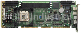
Advantech 1906618608 CPU Boards. Socket 478 | Pentium 4/Celeron Processor | VGA/Dual Gigabit LAN | H...
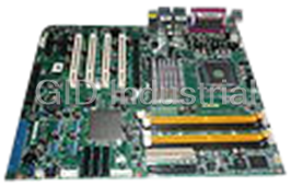
Advantech 1906957112 CPU Board
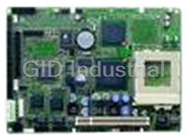
Socket 370 SBC with 3 LAN, and VGA/LCD
LGA 775 Core 2 Duo/Pentium D/ Pentium 4/Celeron D Processor-based ATX with DDR2/PCIe/Dual GbE LAN
Request a Quote

The quote request has been received
Close

Facing challenges or have inquiries? Feel free to contact us!
Call Us +1-469-283-2440
What they say about us
FANTASTIC RESOURCE
One of our top priorities is maintaining our business with precision, and we are constantly looking for affiliates that can help us achieve our goal. With the aid of GID Industrial, our obsolete product management has never been more efficient. They have been a great resource to our company, and have quickly become a go-to supplier on our list!
Bucher Emhart Glass
EXCELLENT SERVICE
With our strict fundamentals and high expectations, we were surprised when we came across GID Industrial and their competitive pricing. When we approached them with our issue, they were incredibly confident in being able to provide us with a seamless solution at the best price for us. GID Industrial quickly understood our needs and provided us with excellent service, as well as fully tested product to ensure what we received would be the right fit for our company.
Fuji
HARD TO FIND A BETTER PROVIDER
Our company provides services to aid in the manufacture of technological products, such as semiconductors and flat panel displays, and often searching for distributors of obsolete product we require can waste time and money. Finding GID Industrial proved to be a great asset to our company, with cost effective solutions and superior knowledge on all of their materials, it’d be hard to find a better provider of obsolete or hard to find products.
Applied Materials
CONSISTENTLY DELIVERS QUALITY SOLUTIONS
Over the years, the equipment used in our company becomes discontinued, but they’re still of great use to us and our customers. Once these products are no longer available through the manufacturer, finding a reliable, quick supplier is a necessity, and luckily for us, GID Industrial has provided the most trustworthy, quality solutions to our obsolete component needs.
Nidec Vamco
TERRIFIC RESOURCE
This company has been a terrific help to us (I work for Trican Well Service) in sourcing the Micron Ram Memory we needed for our Siemens computers. Great service! And great pricing! I know when the product is shipping and when it will arrive, all the way through the ordering process.
Trican Well Service
GO TO SOURCE
When I can't find an obsolete part, I first call GID and they'll come up with my parts every time. Great customer service and follow up as well. Scott emails me from time to time to touch base and see if we're having trouble finding something.....which is often with our 25 yr old equipment.
ConAgra Foods