

 Manufacturers
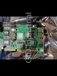
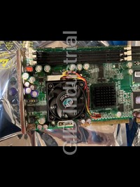
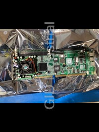
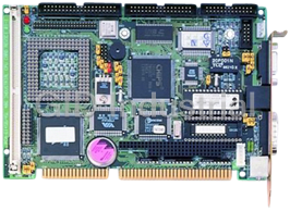
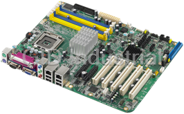
ADVANTECH PCA-6180E


Specifications
Form Factor
PICMG 1.0
Ethernet Chipset
Intel 82562ET
BIOS
Award BIOS, Intel FWH 4 Mb
Chipset
Intel 815E (B) supports 100/133 MHz FSB
CPU
Intel Pentium III/Celeron up to 1.26/1 GHz/850 MHz
Environment
Operating temperature: 0 ~ 60 C (32 ~ 140 F) (depend on CPU used) Power supply voltage: +5 V, 12 V Board size: 338 x 122 mm (13.3" x 4.8")
Expansion Interface
PCI/ISA bus, PICMG compliant
FDD
Supports up to two floppy disk drives. BIOS enabled/disabled. Also supports Japanese Floppy Mode 3
HyperTransport™ Technology
Two 6-pin mini-DIN connector is located on the mounting bracket for easy connection to a keyboard or PS/2 mouse. An on-board keyboard pin header connector is also available
IDE Interface
Supports up to four IDE large hard disk drives or other enhanced IDE devices. Suports PIO Mode 4 (16.67 MB/sec data transfer rate) and Ultra DMA33/66/100 (33/66/100 MB/sec data transfer rate)
ISA
ITE8888F PCI-ISA bridge with ISA High Drive, up to 64 mA
LAN
Supports optional dual 10/100Base-T Ethernet networking Controller: chipset 82562 built-in / Intel 82559
Parallel
Configurable to LPT1, LPT2, LPT3 or disabled. Supports SPP/EPP
PCI Express
Supports 32-bit PCI interface and Ultra 160 SCSI or legacy single-ended devices; data transfer rates up to 160 MB/sec Chipset: Adaptec AIC-7892
Processor
Intel Celeron
Serial
Two RS-232 ports with 16C550 UARTs (or compatible) with 16-byte FIFO buffer. Supports speeds up to 115.2 Kbps. Ports can be individually configured to COM1, COM2 or disabled
USB
4 ports`
VGA
Supports AGP 2X, 133 MHz Controller: Intel 815E built-in
VRAM
Share memory architecture (1-11 MB)
Watchdog Timer
Can generate a system reset or IRQ11. The watchdog timer is programmable with each unit equal to one second or one minute (255 level)
Features
- Intel 815E (B) chipset, supports 100/133 MHz FSB
- ISA High Drive 64 mA (HISA)
- On-board AGP / VGA
- On-board optional dual 10/100Base-T networking controller
- Pentium III/Celeron processor up to 1.26/1 GHz/850 MHz
- Three DIMM sockets for SDRAM up to 512 MB
Datasheet

Extracted Text
PCA-6180
®
Full-size socket 370 Intel
® ®
Pentium III / Celeron
processor based
PCI/ISA-bus CPU card
Copyright notice
This document is copyrighted, 2000, by Advantech Co., Ltd. All
rights are reserved. Advantech Co., Ltd. reserves the right to make
improvements to the products described in this manual at any time
without notice.
No part of this manual may be reproduced, copied, translated or
transmitted in any form or by any means without the prior written
permission of Advantech Co., Ltd. Information provided in this
manual is intended to be accurate and reliable. However, Advantech
Co., Ltd. assumes no responsibility for its use, nor for any in-
fringements upon the rights of third parties which may result from its
use.
Acknowledgements
• AWARD is a trademark of AWARD Software, Inc.
IBM and PC are trademarks of International Business Machines
Corporation.
® ® ®
, Pentium III, and Celeron are trademarks of Intel Corpora-
Intel
tion.
MS-DOS is a trademark of Microsoft Corporation.
SMC is a trademark of Standard Microsystems Corporation.
WinBond is a trademark of Winbond Corporation.
Adaptec is a registered trademark of Adaptec, Inc.
All other product names or trademarks are the properties of their
respective owners.
Part No. 2006618000
1st Edition Printed in Taiwan Dec. 2000
A Message to the Customer
Advantech customer services
Each and every Advantech product is built to the most exacting
specifications to ensure reliable performance in the harsh and
demanding conditions typical of industrial environments. Whether
your new Advantech equipment is destined for the laboratory or the
factory floor, you can be assured that your product will provide the
reliability and ease of operation for which the name Advantech has
come to be known.
Your satisfaction is our primary concern. Here is a guide to
Advantech’s customer services. To ensure you get the full benefit of
our services, please follow the instructions below carefully.
Technical support
We want you to get the maximum performance from your products.
So if you run into technical difficulties, we are here to help. For the
most frequently asked questions, you can easily find answers in your
product documentation. These answers are normally a lot more
detailed than the ones we can give over the phone.
So please consult this manual first. If you still cannot find the answer,
gather all the information or questions that apply to your problem,
and with the product close at hand, call your dealer. Our dealers are
well trained and ready to give you the support you need to get the
most from your Advantech products. In fact, most problems reported
are minor and are able to be easily solved over the phone.
In addition, free technical support is available from Advantech
engineers every business day. We are always ready to give advice on
application requirements or specific information on the installation
and operation of any of our products.
PCA-6180 Series comparison table
Model PCA-6180E PCA-6180E2 PCA-6180SE PCA-6180F
Ţ Ţ
CPU: Intel Pentium III /
V V V V V V V V V V V V V V V V
Ţ
Celeron socket 370
Ţ
System chipset: Intel 815E
V V V V V V V V V V V V V V V V
BIOS: Award P&P BIOS V V V V V V V V V V V V V V V V
Max. system RAM: 512MB V V V V V V V V V V V V V V V V
ISA High Drive V V V V V V V V
V V V V V V V V
4 USB Ports 4
4 4 4
2 EIDE connectors
V V V V V V V V V V V V V V V V
2 serial, 1 parallel ports V V V V V V V V V V V V V V V V
Chipset integrated VGA
V V V V V V V V V V V V V V V V
(AGP)
LAN: 10/100Base-T Ethernet SINGLE DUAL SINGLE DUAL
SCSI: 32-bit PCI Ultra 160 SCSI
------ ------ ------ ------ ------ ------ ------ ------ V V V V V V V V
(Adaptec AIC-7892 chipset)
Product warranty
Advantech warrants to you, the original purchaser, that each of its
products will be free from defects in materials and workmanship for
two years from the date of purchase.
This warranty does not apply to any products which have been
repaired or altered by persons other than repair personnel authorized
by Advantech, or which have been subject to misuse, abuse, accident
or improper installation. Advantech assumes no liability under the
terms of this warranty as a consequence of such events.
If an Advantech product is defective, it will be repaired or replaced at
no charge during the warranty period. For out-of-warranty repairs,
you will be billed according to the cost of replacement materials,
service time and freight. Please consult your dealer for more details.
If you think you have a defective product, follow these steps:
1. Collect all the information about the problem encountered. (For
example, type of PC, CPU speed, Advantech products used, other
hardware and software used, etc.) Note anything abnormal and list
any on-screen messages you get when the problem occurs.
2. Call your dealer and describe the problem. Please have your
manual, product, and any helpful information readily available.
3. If your product is diagnosed as defective, obtain an RMA (return
material authorization) number from your dealer. This allows us
to process your return more quickly.
4. Carefully pack the defective product, a fully-completed Repair
and Replacement Order Card and a photocopy proof of purchase
date (such as your sales receipt) in a shippable container. A
product returned without proof of the purchase date is not eligible
for warranty service.
5. Write the RMA number visibly on the outside of the package and
ship it prepaid to your dealer.
Initial Inspection
Before you begin installing your card, please make sure that the
following materials have been shipped:
® ®
1 PCA-6180 socket 370 Pentium III / Celeron processor-based
single board computer
1 PCA-6180 Startup Manual
1 CD with driver utility and manual (in PDF format)
2 SCSI driver disks (optional)
1 FDD cable
2 Ultra ATA 100 HDD cables, P/N: 1701400452
1 printer (parallel port) cable & COM port cable kit, P/N:
1700060305
1 ATX-to-PS/2 power cable, P/N: 1700000450
1 ivory cable for PS/2 keyboard and PS/2 mouse, P/N:
1700060202
1 single-slot bracket, P/N: 1962159010
1 USB cable adapter (optional), P/N: 1700100170
If any of these items are missing or damaged, contact your distributor
or sales representative immediately.
We have carefully inspected the PCA-6180 mechanically and
electrically before shipment. It should be free of marks and scratches
and in perfect working order upon receipt.
As you unpack the PCA-6180, check it for signs of shipping damage.
(For example, damaged box, scratches, dents, etc.) If it is damaged or
it fails to meet the specifications, notify our service department or
your local sales representative immediately. Also notify the carrier.
Retain the shipping carton and packing material for inspection by the
carrier. After inspection, we will make arrangements to repair or
replace the unit.
Contents
Chapter 1 Hardware Configuration ...............................1
1.1 Introduction ........................................................................2
1.2 Features ...............................................................................3
1.3 Specifications ......................................................................5
1.3.1 System .........................................................................5
1.3.2 Memory .......................................................................5
1.3.3 Input/Output ................................................................5
1.3.4 VGA interface .............................................................. 6
1.3.5 SCSI interface..............................................................6
1.3.6 Ethernet LAN ..............................................................6
1.3.7 Industrial features ........................................................ 6
1.3.8 Mechanical and environmental specifications .............. 6
1.4 Board Layout: Main Features ........................................... 8
1.5 Jumpers and Connectors ...................................................9
1.6 Location of Jumpers and Connectors ............................12
1.7 Safety Precautions ............................................................ 13
1.8 Jumper Settings ................................................................ 14
1.8.1 How to set the jumpers..............................................14
1.8.2 CMOS clear (J1) ........................................................14
1.8.3 Watchdog timer output (J2) .......................................15
1.9 System Memory ................................................................ 16
1.9.1 Sample calculation: DIMM memory capacity ............ 16
1.9.2 Supplementary information about DIMMs ................ 17
1.10 Memory Installation Procedures ..................................... 18
1.11 Cache Memory .................................................................. 18
1.12 CPU Installation ...............................................................19
Chapter 2 Connecting Peripherals ..............................21
2.1 Introduction ......................................................................22
2.2 Primary (CN1) and Secondary (CN2) IDE Connectors . 22
2.3 Floppy Drive Connector (CN3) .......................................23
2.4 Parallel Port (CN4) ........................................................... 23
2.5 SCSI Connector (CN5).....................................................24
2.6 USB Ports (CN31 and CN32)...........................................25
2.7 VGA Connector (CN7).....................................................25
2.8 10/100Base-T Ethernet Connectors (CN8 and CN34) .... 26
2.9 Serial Ports (CN9: COM1; CN10: COM2) ..................... 26
2.10 PS/2 Keyboard and Mouse Connectors (CN11 and
CN33) .................................................................................28
2.11 External Keyboard Connector (CN12) ........................... 28
2.12 Infrared (IR) Connector (CN13) ..................................... 29
2.13 CPU Fan Connector (CN14) ............................................29
2.14 Front Panel Connectors (CN16, CN17, CN18, CN19,
CN21 and CN22) ...............................................................30
2.14.1 Keyboard lock and power LED (CN16) ..................30
2.14.2 External speaker (CN17) ......................................... 30
2.14.3 Reset (CN18) ...........................................................30
2.14.4 HDD LED (CN19) ..................................................31
2.14.5 ATX soft power switch (CN21) ...............................31
2.15 ATX Power Control Connectors (CN20 and CN21) ......31
2.15.1 ATX feature connector (CN20) and soft power
switch connector (CN21) .................................................... 31
2.15.2 Controlling the soft power switch ............................ 32
2.16 SM Bus Connector (CN23) ..............................................32
Chapter 3 Award BIOS Setup.......................................33
3.1 Introduction ......................................................................34
3.2 Entering Setup...................................................................34
3.3 Standard CMOS Setup ..................................................... 35
3.3.1 CMOS RAM backup .................................................35
3.4 Advanced BIOS Features ................................................. 36
3.4.1 Virus Warning ............................................................ 36
3.4.2 CPU Internal Cache / External Cache........................36
3.4.3 CPU L2 Cache ECC Checking ..................................37
3.4.4 Quick Power On Self Test .........................................37
3.4.5 First/Second/Third/Other Boot Device ...................... 37
3.4.6 Swap Floppy Drive .................................................... 37
3.4.7 Boot UP Floppy Seek ................................................37
3.4.8 Boot Up NumLock ....................................................37
3.4.9 Gate A20 Option ........................................................ 38
3.4.10 Typematic Rate Setting ............................................ 38
3.4.11 Typematic Rate (Chars/Sec) ....................................38
3.4.12 Typematic Delay (msec) ..........................................38
3.4.13 Security Option ........................................................ 38
3.4.14 OS Select for DRAM > 64MB ................................39
3.4.15 Report No FDD For Win 95 ....................................39
3.5 Advanced Chipset Features .............................................. 39
3.5.1 SDRAM CAS Latency Time ..................................... 40
3.5.2 SDRAM Cycle Time Tras/Trc ...................................40
3.5.3 SDRAM RAS-to-CAS Delay ..................................... 40
3.5.4 SDRAM RAS Precharge Time ..................................40
3.5.5 System BIOS Cacheable ............................................41
3.5.6 Video Bios Cacheable ................................................ 41
3.5.7 Memory Hole At 15M-16M ...................................... 41
3.5.8 CPU Latency Timer ..................................................41
3.5.9 Delayed Transaction .................................................. 41
3.5.10 AGP Graphics Aperture Size (MB) ......................... 41
3.5.11 On-Chip Video Window Size ................................... 42
3.6 Integrated Peripherals ......................................................42
3.6.1 On-Chip Primary/Secondary PCI IDE ......................42
3.6.2 IDE Primary Master/Slave PIO/UDMA Mode,
IDE Secondary Master/Slave PIO/UDMA Mode (Auto) .... 42
3.6.3 USB Controller .......................................................... 43
3.6.4 USB Keyboard Support .............................................43
3.6.5 Init Display First ........................................................ 43
3.6.6 IDE HDD Block Mode ..............................................43
3.6.7 Onboard FDC Controller ........................................... 43
3.6.8 Onboard Serial Port 1 (3F8H/IRQ4)..........................43
3.6.9 Onboard Serial Port 2 (2F8H/IRQ3)..........................43
3.6.10 UART Mode Select .................................................44
3.6.11 RxD, TxD Active ..................................................... 44
3.6.12 IR Transmission Delay............................................. 44
3.6.13 UR2 Duplex Mode ................................................... 44
3.6.14 Use IR Pins..............................................................45
3.6.15 Onboard Parallel Port (378H/IRQ7) ........................ 45
3.6.16 Parallel Port Mode (ECP + EPP) ............................45
3.6.17 EPP Mode Select.....................................................45
3.6.18 ECP Mode Use DMA..............................................45
3.7 Power Management Setup ............................................... 46
3.7.1 Power Management ...................................................46
3.7.2 HDD Power Down ....................................................46
3.7.3 Soft-Off by PWR-BTTN ..........................................46
3.7.4 PowerOn By LAN .....................................................47
3.7.5 PowerOn By Modem ................................................47
3.7.6 PowerOn By Alarm ...................................................47
3.7.8 CPU Thermal-Throttling ........................................... 47
3.8 PnP/PCI Configurations .................................................. 47
3.8.1 Resources controlled by: ............................................ 47
3.8.2 PnP OS Installed .......................................................47
3.8.3 Reset Configuration Data ........................................... 48
3.8.4 PCI/VGA Palette Snoop ............................................48
3.9 PC Health Status ..............................................................48
3.9.1 CPU Warning Temperature .......................................48
3.9.2 Current System Temp. ..............................................48
3.9.3 Current CPU Temperature ........................................49
3.9.4 Current CPUFAN Speed ...........................................49
3.9.5 +5V/+12V/-12V/-5V ..................................................49
3.9.6 Shutdown Temperature .............................................49
3.10 Load Setup Defaults .........................................................50
3.11 Password Setting ............................................................... 50
3.12 Save & Exit Setup .............................................................51
3.13 Exit Without Saving ......................................................... 51
Chapter 4 Chipset Software Installation (CSI) Utility.53
4.1 Before You Begin ..............................................................54
4.2 Introduction ......................................................................54
4.3 Installing the CSI Utility ..................................................56
Chapter 5 AGP SVGA Setup ........................................59
5.1 Introduction ......................................................................60
5.2 Installation ........................................................................60
Chapter 6 LAN Configuration.......................................65
6.1 Introduction ......................................................................66
6.2 Features .............................................................................66
6.3 Installation ........................................................................67
6.4 Windows 95/98/2000 Drivers Setup Procedure ............... 68
6.5 Windows NT Drivers Setup Procedure ........................... 75
6.6 Windows 98SE/ME Drivers Setup Procedure ................. 78
6.7 Windows NT Wake-on-LAN Setup Procedure ............... 85
Chapter 7 Ultra ATA 100 Storage Driver Setup ..........87
7.1 Introduction ......................................................................88
7.2 Features .............................................................................88
7.3 Installation ........................................................................89
7.4 Displaying Driver Information ........................................ 93
Chapter 8 Onboard Security Setup .............................95
8.1 Introduction ......................................................................96
8.2 Installation ........................................................................96
8.3 Windows 9X Drivers Setup Procedure ............................ 97
8.4 Windows NT Drivers Setup Procedure ......................... 100
8.5 Using the OBS Hardware Doctor Utility ...................... 104
Appendix A Programming the Watchdog Timer....... 107
A.1 Programming the Watchdog Timer ............................... 108
A.1.1 Watchdog timer overview ...................................... 108
A.1.2 Reset/ Interrupt selection ....................................... 108
A1.3 Programming the Watchdog Timer ......................... 108
A.1.4 Example Program ................................................... 111
Appendix B Pin Assignments ..................................... 117
B.1 IDE Hard Drive Connector (CN1, CN2) ....................... 118
B.2 Floppy Drive Connector (CN3) ..................................... 119
B.3 Parallel Port Connector (CN4) ...................................... 120
B.4 SCSI Connector (CN5)...................................................121
B.5 USB Connector (CN6) ....................................................122
B.6 VGA Connector (CN7)...................................................122
B.7 Ethernet 10/100Base-T RJ-45 Connector
(CN8, CN34)....................................................................123
B.8 COM1/COM2 RS-232 Serial Port (CN9, CN10) .......... 123
B.9 Keyboard and Mouse Connnector (CN11) ...................124
B.10 External Keyboard Connector (CN12) ......................... 124
B.11 IR Connector (CN13) .....................................................125
B.12 CPU Fan Power Connector (CN14) .............................. 125
B.13 Power LED and Keylock Connector (CN16) ............... 126
B.14 External Speaker Connector (CN17) ............................. 126
B.15 Reset Connector (CN18) ................................................127
B.16 HDD LED Connector (CN19) ........................................ 127
B.17 ATX Feature Connector (CN20) .................................... 127
B.18 ATX Soft Power Switch (CN21) ..................................... 128
B.19 H/W Monitor Alarm (CN22) ......................................... 128
B.20 SM Bus Connector (CN23) ............................................128
B.21 Extension I/O Board Connector (CN27) ...................... 129
B.22 Extension I/O Board Connector (CN28) ...................... 129
B.23 PS/2 Mouse Connector (CN33) .....................................130
B.24 System I/O Ports ............................................................. 131
B.25 DMA Channel Assignments ........................................... 132
B.26 Interrupt Assignments .................................................... 132
B.27 1st MB Memory Map ..................................................... 133
B.28 PCI Bus Map................................................................... 133
Figures
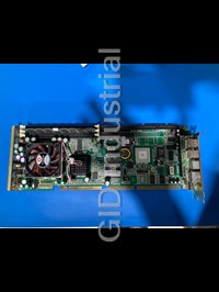
Figure 1-1: Board layout: main features .......................................................................... 8
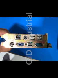
Figure 1-2: Rear plate ..................................................................................................... 9
Figure 1-3: Location of jumpers and connecters ........................................................... 12
Figure 3-1: Awards BIOS setup initial screen ............................................................... 34
Figure 3-2: Standard CMOS features screen ................................................................ 35
Figure 3-3: Awards BIOS features screen (1) .............................................................. 36
Figure 3-4: Awards BIOS features screen (2) .............................................................. 39
Figure 3-5: Advanced chipset features screen .............................................................. 40
Figure 3-6: Integrated peripherals (1) ........................................................................... 42
Figure 3-7: Integrated peripherals (2) ........................................................................... 44
Figure 3-8: Power management setup screen ............................................................... 46
Figure 3-9: PnP/PCI configurations screen ................................................................... 48
Figure 3-10: PC health status screen ............................................................................ 49
Tables
Table 1-1: Jumpers ............................................................................................................ 9
Table 1-2: Connectors ...................................................................................................... 10
Table 1-3: CMOS clear (J1) ............................................................................................. 14
Table 1-4: Watchdog timer output (J2) ............................................................................. 15
Table 1-5: DIMM module allocation table ......................................................................... 16
Table 1-6: DIMM memory capacity sample calculation ................................................... 16
Table 2-1: Serial port connections (COM1, COM2) .......................................................... 27
Table 2-2: PS/2 or ATX power supply LED status ............................................................ 30
Table A-1: Watchdog timer registers ............................................................................. 110
Table B-1: IDE hard drive connector (CN1, CN2) ............................................................ 118
Table B-2: Floppy drive connector (CN3) ........................................................................ 119
Table B-3: Parallel port connector (CN4) ........................................................................ 120
Table B-4: SCSI connector (CN5) .................................................................................. 121
Table B-5: USB1/USB2 connector (CN6) ....................................................................... 122
Table B-6: VGA connector (CN7) ................................................................................... 122
Table B-7: Ethernet 10/100Base-T RJ-45 connector (CN8, CN34) ................................. 123
Table B-8: COM1/COM2 RS-232 serial port (CN9, CN10) ............................................. 123
Table B-9: Keyboard and mouse connector (CN11) ....................................................... 124
Table B-10: External keyboard connector (CN12) .......................................................... 124
Table B-11: IR connector (CN13) .................................................................................... 125
Table B-12: CPU fan power connector (CN14) ............................................................... 125
Table B-13: Power LED and keylock connector (CN16) ................................................. 126
Table B-14: External speaker (CN17) ............................................................................ 126
Table B-15: Reset connector (CN18) ............................................................................. 127
Table B-16: HDD LED connector (CN19) ....................................................................... 127
Table B-17: ATX feature connector (CN20) ..................................................................... 127
Table B-18: ATX soft power switch (CN21) ..................................................................... 128
Table B-19: H/W monitor alarm (CN22) ......................................................................... 128
Table B-20: ATX soft power switch (CN21) ..................................................................... 128
Table B-21: Extension I/O board connector (CN27) ....................................................... 129
Table B-22: Extension I/O board connector (CN28) ....................................................... 129
Table B-23: PS/2 mouse connector (CN33) ................................................................... 130
Table B-24: System I/O ports ........................................................................................ 131
Table B-25: DMA channel assignments ......................................................................... 132
Table B-26: Interrupt assignments ................................................................................. 132
Table B-27: 1st MB memory map .................................................................................. 133
1
Hardware Configuration
This chapter gives background informa-
tion on the PCA-6180. It then shows you
how to configure the card to match your
application and prepare it for installation
into your PC.
Sections include:
Introduction
Features
Specifications
Board Layout
Jumpers and Connectors
Location of Jumpers and Connectors
Safety Precautions
Jumper Settings
System Memory
Memory Installation Procedures
Cache Memory
CPU Installation
CHAPTER
1.1 Introduction
The PCA-6180 Series all-in-one industrial grade CPU card uses
® ® ®
Intel 's highly acclaimed Pentium III / Celeron processor, together
®
with the Intel 815E chipset. The card works with standard ISA- or
PCI/ISA-bus passive backplanes.
The CPU provides 256/128 KB on-CPU L2 cache, eliminating the
need for external SRAM chips. It has two PCI EIDE interfaces (for
up to four devices) and a floppy disk drive interface (for up to two
devices). Other features include two RS-232 serial ports (16C550
UARTs with 16-byte FIFO or compatible), one enhanced parallel port
(supports SPP/EPP/ECP) and four USB (Universal Serial Bus) ports.
The PCI enhanced IDE controller supports Ultra ATA/100/66/33 and
PIO Mode 4 operation. This provides data transfer rates of 100/66/
33 MB/sec. System BIOS supports boot-up from an IDE HDD/CD-
ROM, SCSI HDD/CD-ROM, LS-120, ZIP-100, FDD, and LAN.
A backup of CMOS data is stored in the Flash memory, which
protects data even after a battery failure. Also included is a 255-level
watchdog timer, which resets the CPU or generates an interrupt if a
program cannot be executed normally. This enables reliable opera-
tion in unattended environments.
The PCA-6180 Series offers several impressive industrial features
such as a chipset integrated VGA (AGP) controller, a PCI Ultra 160
SCSI controller, dual 10/100Base-T networking controllers, three
DIMM slots for a total of 512 MB SDRAM memory, and an ISA
High Drive. All these make it an ideal choice for applications that
require both high performance and full functionality.
Note: Some of the features mentioned above are not
available with all models. For more information about
the specifications of a particular model, see
Section 1.3: Specifications.
2 PCA-6180 User's Manual
1.2 Features
1. Fan status monitoring and alarm: To prevent system overheating
and damage, the CPU fan can be monitored for speed and failure.
The fan is set for its normal RPM range and alarm thresholds.
2. Temperature monitoring and alert: To prevent system overheating
and damage, the CPU card supports processor thermal sensing and
auto-protection.
3. Voltage monitoring and alert: System voltage levels are monitored
to ensure stable current flows to critical components. Voltage
specifications will become even more critical for processors of the
future. Thus monitoring will become ever more necessary to ensure
proper system configuration and management.
4. ATX soft power switch: Through the BIOS, the power button can
be defined as the "Standby" (aka "Suspend" or "Sleep") button or
as the "Soft-Off" button (see Section 3.6.6 Soft-off by PWR-BTN).
Regardless of the setting, pushing the power button for more than
4 seconds will enter the Soft-Off mode.
5. Power-on by modem (requires modem): This allows a computer
to be turned on remotely through an internal or external modem.
Users can thus access information on their computers from
anywhere in the world.
6. Remote wake-up: This feature (aka "Wake-on-LAN") allows you
to remotely power up your system through your network by
sending a wake-up frame or signal. With this feature, you can
remotely upload/download data to/from systems during off-peak
hours.
7. Message LED: Chassis LEDs now act as information providers.
The way a particular LED illuminates indicates the stage the
computer is in. A single glimpse provides useful information to the
user.
8. Jumperless mode: When enabled, this allows changes of
Chapter 1 Hardware Configuration 3
processor settings and Vcore voltages all through the BIOS setup.
9. CMOS RAM backup: When BIOS CMOS setup has been
completed, data in the CMOS RAM is automatically backed up to
the Flash ROM. This is particularly useful in industrial environ-
ments which may cause soft errors. Upon such an error, BIOS will
check the data and automatically restore the original data for
rebooting.
10.More:
Additional metal bracket for CPU stabilization
Power on by alarm: Powers up your computer at a certain
time
Virus warning: During and after system boot-up, any attempt
to write to the boot sector or partition table of the hard disk
drive will halt the system. In this case, a warning message will
be displayed. You can then run your anti-virus program to
locate the problem.
4 PCA-6180 User's Manual
1.3 Specifications
1.3.1 System
® ®
CPU: Intel Pentium III processor up to 933 MHz, Celeron up to
733 MHz, FSB 66/100/133 MHz.
Firmware hub: Provides security enhancements on computer
platforms by supporting Random Number Generator (RNG).
BIOS: Award Flash BIOS.
®
System Chipset: Intel 815E.
PCI enhanced IDE hard disk drive interface: Supports up to four
IDE (AT-bus) large hard disk drives or other enhanced IDE
devices. Supports PIO mode 4 (16.67 MB/s data transfer rate) and
Ultra ATA 100/66/33 (100/66/33 MB/s data transfer rate). BIOS
enabled/disabled.
Floppy disk drive interface: Supports up to two floppy disk
drives, 5¼" (360 KB and 1.2 MB) and/or 3½" (720 KB, 1.44 MB,
and 2.88 MB). BIOS enabled/disabled.
1.3.2 Memory
RAM: Up to 512 MB in three available 168-pin DIMM sockets.
Supports PC100/ PC133-compliant SDRAMs.
ECC (parity DRAM): not supported.
1.3.3 Input/Output
Bus interface: PCI/ISA bus, PICMG compliant.
Enhanced parallel port: Configurable to LPT1 or disabled.
Standard DB-25 female connector provided. Supports EPP/ECP.
Serial ports: Two RS-232 ports with 16C550 UARTs (or
compatible) with 16-byte FIFO buffer. Supports speeds up to 115.2
Kbps. Ports can be individually configured to COM1, COM2, or
disabled.
Chapter 1 Hardware Configuration 5
Keyboard and PS/2 mouse connector: A 6-pin mini-DIN
connector is located on the mounting bracket for easy connection
to a keyboard or a PS/2 mouse. An onboard keyboard pin header
connector is also available.
®
HISA : ISA bus high-driving capability up to 64 mA.
1.3.4 VGA interface
Supports AGP 2X, 133 MHz.
Controller: Chipset integrated.
1.3.5 SCSI interface
PCI SCSI: Supports 32-bit PCI interface and Ultra 160 SCSI or
legacy single-ended devices; data transfer up to 160 MB/sec.
Chipset: Adaptec AIC-7892.
1.3.6 Ethernet LAN
Supports dual 10/100Base-T Ethernet networking.
®
Chipset: One onboard Intel GD82559 and one chipset integrated
LAN controller.
1.3.7 Industrial features
Watchdog timer: Can generate a system reset or IRQ11. The
watchdog timer is programmable, from one second to 255 minutes
(255 levels). See Appendix A for the programming details.
1.3.8 Mechanical and environmental specifications
Operating temperature: 0°~60° C (32° ~ 140° F).
Note: The temperature depends on which CPU is used.
©
The range is 0°~50° (32°~122°F) for a Pentium III
933 MHz.
Storage temperature: 0°~ 60° C (32° ~ 140° F).
Humidity: 20 ~ 95% non-condensing.
6 PCA-6180 User's Manual
Power supply voltage: +5 V, ±12 V.
Power consumption (depends on CPU and memory):
+5 V @ 6 A (typical, with Pentium III 866 MHz and 128MB
SDRAM).
Board size: 338 x 122 mm (13.3" x 4.8").
Board weight: 0.5 kg (1.2 lb).
Chapter 1 Hardware Configuration 7
1.4 Board Layout: Main Features
Figure 1-1: Board layout: main features
8 PCA-6180 User's Manual
Figure 1-2: Rear plate
1.5 Jumpers and Connectors
Connectors on the PCA-6180 board link it to external devices such
as hard disk drives and a keyboard. In addition, the board has a number
of jumpers used to configure your system for your application.
The tables below list the function of each of the board jumpers and
connectors. Later sections in this chapter give instructions on setting
the jumpers. Chapter 2 gives instructions for connecting external
devices to your card.
Table 1-1: Jumpers
Label Function
J1 CMOS clear
J2 Watchdog timer output selection
Chapter 1 Hardware Configuration 9
Table 1-2: Connectors
Label Function
CN1 Primary IDE connector
CN2 Secondary IDE connector
CN3 Floppy drive connector
CN4 Parallel port
CN5 SCSI connector
CN6 USB port
CN7 VGA connector
CN8 10/100Base-T Ethernet connector 1
CN9 Serial port: COM1
CN10 Serial port: COM2
CN11 PS/2 keyboard and mouse connector
CN12 External keyboard connector
CN13 Infrared (IR) connector
CN14 CPU fan connector
CN16 Keyboard lock and power LED
CN17 External speaker
CN18 Reset connector
CN19 HDD LED connector
CN20 ATX feature connector
CN21 ATX soft power switch
CN22 H/W monitor alarm: close - enable OBS alarm
open - disable OBS alarm
CN23 SM bus connector
CN26 Reserved
CN27 Connector to extension I/O board
CN28 Connector to extension I/O board
10 PCA-6180 User's Manual
Extension I/O board
CN31 USB port 0,1
CN32 USB port 2,3
CN33 PS/2 mouse connector
CN34 10/100Base-T Ethernet connector 2
Chapter 1 Hardware Configuration 11
1.6 Location of Jumpers and Connectors
Figure 1-3: Location of jumpers and connecters
Note: See Chapter 2 for the location of CN31~CN34.
12 PCA-6180 User's Manual
1.7 Safety Precautions
Warning! Always completely disconnect the power cord from
your chassis whenever you work with the hardware.
Do not make connections while the power is on.
Sensitive electronic components can be damaged
by sudden power surges. Only experienced
electronics personnel should open the PC chassis.
Caution! Always ground yourself to remove any static charge
before touching the CPU card. Modern electronic
devices are very sensitive to static electric charg-
es. As a safety precaution, use a grounding wrist
strap at all times. Place all electronic components
on a static-dissipative surface or in a static-
shielded bag when they are not in the chassis.
Chapter 1 Hardware Configuration 13
1.8 Jumper Settings
This section provides instructions on how to configure your card by
setting the jumpers. It also includes the card's default settings and
your options for each jumper.
1.8.1 How to set the jumpers
You configure your card to match the needs of your application by
setting the jumpers. A jumper is a metal bridge that closes an
electrical circuit. It consists of two metal pins and a small metal clip
(often protected by a plastic cover) that slides over the pins to
connect them. To “close” (or turn ON) a jumper, you connect the pins
with the clip. To “open” (or turn OFF) a jumper, you remove the clip.
Sometimes a jumper consists of a set of three pins, labeled 1, 2, and
3. In this case you connect either pins 1 and 2, or 2 and 3.
A pair of needle-nose pliers may be useful when setting jumpers.
1.8.2 CMOS clear (J1)
The PCA-6180 CPU card contains a jumper that can erase CMOS
data and reset the system BIOS information. Normally this jumper
should be set with pins 1-2 closed. If you want to reset the CMOS
data, set J1 to 2-3 closed for just a few seconds, and then move the
jumper back to 1-2 closed. This procedure will reset the CMOS to its
default setting.
Table 1-3: CMOS clear (J1)
Function Jumper setting
1
* Keep CMOS data 1-2 closed
1
Clear CMOS data 2-3 closed
* default setting
14 PCA-6180 User's Manual
1 1
1.8.3 Watchdog timer output (J2)
The PCA-6180 contains a watchdog timer that will reset the CPU or
send a signal to IRQ11 in the event the CPU stops processing. This
feature means the PCA-6180 will recover from a software failure or an
EMI problem. The J2 jumper settings control the outcome of what the
computer will do in the event the watchdog timer is tripped.
Table 1-4: Watchdog timer output (J2)
Function Jumper setting
1
IRQ11 1-2 closed
1
* Reset 2-3 closed
* default setting
Note: The interrupt output of the watchdog timer is a low
level signal. It will be held low until the watchdog
timer is reset.
Chapter 1 Hardware Configuration 15
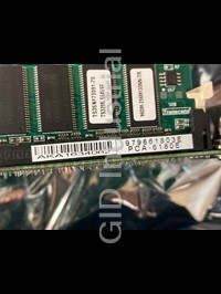
1.9 System Memory
The top-left edge of the PCA-6180 contains three sockets for
168-pin dual in-line memory modules (DIMMs). All three sockets
use 3.3 V unbuffered synchronous DRAMs (SDRAM). DIMMs are
available in capacities of 16, 32, 64, 128, or 256 MB. The sockets
can be filled in any combination with DIMMs of any size, giving your
PCA-6180 single board computer between 16 MB and 512 MB of
memory. Use the following table to calculate the total DRAM
memory within your computer:
Table 1-5: DIMM module allocation table
Socket number 168-pin DIMM memory
1 (16, 32, 64, 128, or 256 MB) x 1
2 (16, 32, 64, 128, or 256 MB) x 1
3 (16, 32, 64, 128, or 256 MB) x 1
1.9.1 Sample calculation: DIMM memory capacity
Suppose you install a 128 MB DIMM into your PCA-6180's socket 1
and a 32 MB DIMM into sockets 2 and 3. Your total system memory is
192 MB, calculated as follows:
Table 1-6: DIMM memory capacity sample calculation
Socket number 168-pin DIMM memory Total memory
1 128 MB x 1 128 MB
2 32 MB x 1 32 MB
3 32 MB x 1 32 MB
Total memory 192 MB
16 PCA-6180 User's Manual
1.9.2 Supplementary information about DIMMs
Your PCA-6180 can accept SDRAM memory chips (with or without
parity). Also note:
If the PCA-6180 operates at 133 MHz, only use PC/133-compliant
DIMMs. Most systems will not even boot if non-compliant modules
are used. This is due to strict timing issues involved at this speed.
Chips with 9 chips/side support ECC; chips with 8 chips/side do not
support ECC. PCA-6180 does not support ECC.
Single-sided modules are typically 16, 32, or 64 MB; double-sided
modules are usually 32, 64, 128, or 256 MB.
Chapter 1 Hardware Configuration 17
1.10 Memory Installation Procedures
To install DIMMs, first make sure the two handles of the DIMM
socket are in the "open" position (i.e., the handles lean outward).
Slowly slide the DIMM module along the plastic guides on both ends
of the socket. Then press the DIMM module right down into the
socket, until you hear a click. This is when the two handles have
automatically locked the memory module into the correct position of
the DIMM socket. To remove the memory module, just push both
handles outward, and the memory module will be ejected by the
mechanism in the socket.
1.11 Cache Memory
®
Since the second-level (L2) cache has been embedded into the Intel
®
FC-PGA Pentium III processor, you do not have to take care of either
SRAM chips or SRAM modules. The built-in second-level cache in
the processor yields much higher performance than the external
® ®
cache memories. The cache size in the Intel FC-PGA Pentium III
processor is 256 KB. In the Celeron CPU, the cache size is 128KB.
18 PCA-6180 User's Manual
1.12 CPU Installation
®
The PCA-6180 provides a socket 370 for an Intel FC-PGA Pen-
®
tium III processor. The CPU on the board must have a fan or heat
sink attached to prevent overheating.
Warning: Without a fan or heat sink, the CPU will overheat
and cause damage to both the CPU and the moth-
erboard.
To install a CPU, first turn off your system and remove its cover.
Locate the processor socket 370.
1. Make sure the socket 370 lever is in the upright position. To raise
the lever, pull it out to the side a little and raise it as far as it will go.
2. Place the CPU in the empty socket. Follow the instructions that
came with the CPU. If you have no instructions, complete the
following procedure. Carefully align the CPU so it is parallel to the
socket and the notches on the corners of the CPU correspond with
the notches on the inside of the socket. Gently slide the CPU in. It
should insert easily. If it does not insert easily, pull the lever up a
little bit more.
3. Press the lever down. The plate will slide forward. You will feel
some resistance as the pressure starts to secure the CPU in the
socket. This is normal and will not damage the CPU.
When the CPU is installed, the lever should snap into place at the side
of the socket.
Note: To remove a CPU, pull the lever out to the side a
little and raise it as far as it will go. Lift out the CPU.
Chapter 1 Hardware Configuration 19
2
Connecting Peripherals
This chapter tells how to connect
peripherals, switches, and indicators to
the PCA-6180 board.
CHAPTER
2.1 Introduction
You can access most of the connectors from the top of the board
while it is installed in the chassis. If you have a number of cards
installed or have a packed chasis, you may need to partially remove
the card to make all the connections.
Note: If your chassis has only one empty expansion slot
to accommodate the CPU card, you can replace the
standard dual-slot bracket with the single-slot
bracket included in your PCA-6180 package, in
which case you will have to access the connectors
(CN31~34) on the extension I/O board from inside
the chassis.
2.2 Primary (CN1) and Secondary (CN2) IDE
Connectors
You can attach up to four IDE (Integrated Drive Electronics) drives to
the PCA-6180’s built-in controller. The primary (CN1) and second-
ary (CN2) connectors can each accommodate two drives.
Wire number 1 on the cable is red or blue and the other wires are
gray. Connect one end to connector CN1 or CN2 on the CPU card.
Make sure that the red/blue wire corresponds to pin 1 on the connec-
tor (in the upper right hand corner). See Chapter 1 for help finding
the connector.
Unlike floppy drives, IDE hard drives can connect in either position
on the cable. If you install two drives to a single connector, you will
need to set one as the master and the other as the slave. You do this
by setting the jumpers on the drives. If you use just one drive per
connector, you should set each drive as the master. See the documen-
tation that came with your drive for more information.
22 PCA-6180 User's Manual
Connect the first hard drive to the other end of the cable. Wire 1 on
the cable should also connect to pin 1 on the hard drive connector,
which is labeled on the drive circuit board. Check the documentation
that came with the drive for more information.
Connect the second hard drive to the remaining connector (CN2 or
CN1), in the same way as described above.
Note: The PCA-6180 supports the Ultra ATA/100 interface
and requires special IDE cables as well as a
software driver to enable this function. See Chapter
7 for more information.
2.3 Floppy Drive Connector (CN3)
You can attach up to two floppy disk drives to the PCA-6180's
onboard controller. You can use 3.5" (720 KB, 1.44/2.88 MB) drives.
The card comes with a 34-pin daisy-chain drive connector cable. On
one end of the cable is a 34-pin flat-cable connector. On the other end
are two sets of 34-pin flat-cable connector (usually used for 3.5"
drives). The set on the end (after the twist in the cable) connects to the
A: floppy drive. The set in the middle connects to the B: floppy drive.
2.4 Parallel Port (CN4)
Chapter 2 Connecting Peripherals 23
The parallel port is normally used to connect the CPU card to a
printer. The PCA-6180 includes an onboard parallel port, accessed
through a 26-pin flat-cable connector, CN4. The card comes with an
adapter cable which lets you use a traditional DB-25 connector. The
cable has a 26-pin connector on one end and a DB-25 connector on
the other, mounted on a retaining bracket. The bracket installs at the
end of an empty slot in your chassis, giving you access to the
connector.
To install the bracket, find an empty slot in your chassis. Unscrew the
plate that covers the end of the slot. Screw in the bracket in place of
the plate. Next, attach the flat-cable connector to CN4 on the CPU
card. Wire 1 of the cable is red or blue, and the other wires are gray.
Make sure that wire 1 corresponds to pin 1 of CN4. Pin 1 is on the
upper right side of CN4.
2.5 SCSI Connector (CN5)
The PCA-6180 has a 68-pin, dual in-line connector for Ultra 160 SCSI
devices. Connection of SCSI devices requires special attention,
especially when determining the last drive on the SCSI chain. Refer to
Chapter 9 and your device's operating manual for detailed installation
advice.
24 PCA-6180 User's Manual
2.6 USB Ports (CN31 and CN32)
The PCA-6180 provides four ports of USB (Universal Serial Bus)
interface, which gives complete Plug & Play and hot swapping for up
to 127 external devices.The USB interface complies with USB
Specification Rev. 1.0 and is fuse-protected.
The USB interface can be disabled in the system BIOS setup.
2.7 VGA Connector (CN7)
The PCA-6180 includes an AGP SVGA interface that can drive
conventional CRT displays. CN7 is a standard 15-pin D-SUB connec-
tor commonly used for VGA. Pin assignments for CRT connector
CN7 are detailed in Appendix B.
Chapter 2 Connecting Peripherals 25
2.8 10/100Base-T Ethernet Connectors (CN8
and CN34)
The PCA-6180 is equipped with one or two high-performance 32-bit
PCI-bus Ethernet interfaces, which are fully compliant with IEEE
802.3/u 10/100 Mbps CSMA/CD standards. They are supported by all
major network operating systems and are 100% Novell NE-2000
compatible. The RJ-45 jacks on the rear plate provide convenient
10/100Base-T RJ-45 operation.
2.9 Serial Ports (CN9: COM1; CN10: COM2)
26 PCA-6180 User's Manual
The PCA-6180 offers two serial ports, CN9 as COM1 and CN10 as
COM2. These ports can connect to serial devices, such as a mouse or
a printer, or to a communications network.
Table 2-1: Serial port connections (COM1, COM2)
Connector Ports Address Interrupt
CN9 COM1 3F8*, 3E8 IRQ4
CN10 COM2 2F8*, 2E8 IRQ3
* default settings
The IRQ and address ranges for both ports are fixed. However, if you
want to disable the port or change these parameters later, you can do
this in the system BIOS setup.
Different devices implement the RS-232 standard in different ways. If
you are having problems with a serial device, be sure to check the pin
assignments for the connector.
Chapter 2 Connecting Peripherals 27
2.10 PS/2 Keyboard and Mouse Connectors
(CN11 and CN33)
Two 6-pin mini-DIN connectors (CN11 and CN33) on the card mount-
ing bracket provide connection to a PS/2 keyboard and a PS/2 mouse,
respectively. CN11 can also be connected to an adapter cable (P/N:
1700060202, available from Advantech) for connecting to both a PS/
2 keyboard and a PS/2 mouse.
2.11 External Keyboard Connector (CN12)
In addition to the PS/2 mouse/keyboard connector on the
PCA-6180's rear plate, there is also an extra onboard external
keyboard connector. This gives system integrators greater flexibility
in designing their systems.
28 PCA-6180 User's Manual
2.12 Infrared (IR) Connector (CN13)
This connector supports the optional wireless infrared transmitting
and receiving module. This module mounts on the system case. You
must configure the setting through the BIOS setup (see Chapter 3).
2.13 CPU Fan Connector (CN14)
This connector supports cooling fans of 500 mA (6 W) or less.
Chapter 2 Connecting Peripherals 29
2.14 Front Panel Connectors (CN16, CN17,
CN18, CN19, CN21 and CN22)
There are several external switches to monitor and control the
PCA-6180.
2.14.1 Keyboard lock and power LED (CN16)
CN16 is a 5-pin connector for the keyboard lock and power on LED.
Refer to Appendix B for detailed information on the pin assignments.
If a PS/2 or ATX power supply is used, the system's power LED
status will be as indicated below:
Table 2-2: PS/2 or ATX power supply LED status
Power mode LED (PS/2 power) LED (ATX power)
System On On On
System Suspend Fast flashes Fast flashes
System Off Off Slow flashes
2.14.2 External speaker (CN17)
CN17 is a 4-pin connector for an extenal speaker. If there is no
external speaker, the PCA-6180 provides an onboard buzzer as an
alternative. To enable the buzzer, set pins 3-4 as closed.
2.14.3 Reset (CN18)
Many computer cases offer the convenience of a reset button.
Connect the wire from the reset button to CN18.
30 PCA-6180 User's Manual
2.14.4 HDD LED (CN19)
You can connect an LED to connector CN19 to indicate when the
HDD is active.
2.14.5 ATX soft power switch (CN21)
If your computer case is equipped with an ATX power supply, you
should connect the power on/off button on your computer case to
CN21. This connection enables you to turn your computer on and off.
2.15 ATX Power Control Connectors (CN20
and CN21)
Note: Refer to the diagram on the previous page for the
location of CN21.
2.15.1 ATX feature connector (CN20) and soft power
switch connector (CN21)
The PCA-6180 can support an advanced soft power switch function if
an ATX power supply is used. To enable the soft power switch
function:
1. Take the specially designed ATX-to-PS/2 power cable out of the
PCA-6180's accessory bag.
2. Connect the 3-pin plug of the cable to CN20 (ATX feature connec-
tor).
3. Connect the power on/off button to CN21. (A momentary type of
button should be used.)
Note: If you will not be using an ATX power connector,
make sure that pins 2-3 of CN20 are closed.
Chapter 2 Connecting Peripherals 31
Warnings: 1. Make sure that you unplug your power supply
when adding or removing expansion cards or other
system components. Failure to do so may cause
severe damage to both your CPU card and expansion
cards.
2. ATX power supplies may power on if certain
motherboard components or connections are touched
by metallic objects.
Important: Make sure that the ATX power supply can take at
least a 720 mA load on the 5 V standby lead (5VSB).
If not, you may have difficulty powering on your
system and/or supporting the "Wake-on-LAN"
function.
2.15.2 Controlling the soft power switch
Users can also identify the current power mode through the system's
power LED (see Section 2.13.1).
2.16 SM Bus Connector (CN23)
This connector can be used for external devices which need to be
connected to the SM bus (system management bus).
32 PCA-6180 User's Manual
3
Award BIOS Setup
This chapter describes how to set the
card’s BIOS configuration data.
CHAPTER
3.1 Introduction
Award’s BIOS ROM has a built-in setup program that allows users to
modify the basic system configuration. This type of information is
stored in battery-backed memory (CMOS RAM) so that it retains the
setup information when the power is turned off.
3.2 Entering Setup
Turn on the computer and check for the “patch code”. If there is a
number assigned to the patch code, it means that the BIOS supports
your CPU.
If there is no number assigned to the patch code, please contact
Advantech’s applications engineer to obtain an up-to-date patch code
file. This will ensure that your CPU’s system status is valid.
After ensuring that you have a number assigned to the patch code,
press to allow you to enter the setup.
Figure 3-1: Award BIOS Setup initial screen
34 PCA-6180 User’s Manual
3.3 Standard CMOS Setup
Choose the “Standard CMOS Features” option from the “Initial Setup
Screen” menu, and the screen below will be displayed. This menu
allows users to configure system components such as date, time, hard
disk drive, floppy drive, display, and memory.
Figure 3-2: Standard CMOS features screen
3.3.1 CMOS RAM backup
The CMOS RAM is powered by an onboard button cell battery.
When BIOS CMOS Setup has been completed, CMOS RAM data is
automatically backed up to Flash ROM. If conditions in a harsh
industrial enviroment cause a soft error, BIOS will recheck the data and
automatically restore the original data for booting.
Note: If you intend to update CMOS RAM data, you have
to click on “DEL” within two seconds of the “CMOS
checksum error....” display screen message appear-
ing. Then enter the “Setup” screen to modify the data.
If the “CMOS checksum error....” message appears
again and again, please check to see if you need to
replace the battery in your system.
Chapter 3 Award BIOS Setup 35
3.4 Advanced BIOS Features
The “Advanced BIOS Features” screen appears when choosing the
“Advanced BIOS Features” item from the “Initial Setup Screen”
menu. It allows the user to configure the PCA-6180 according to his
particular requirements.
Below are some major items that are provided in the Advanced BIOS
Features screen.
A quick booting function is provided for your convenience. Simply
enable the Quick Booting item to save yourself valuable time.
Figure 3-3: Advanced BIOS features screen (1)
3.4.1 Virus Warning
If enabled, a warning message and alarm beep activates if someone
attempts to write here. The commands are “Enabled” or “Disabled.”
3.4.2 CPU Internal Cache / External Cache
Enabling this feature speeds up memory access. The commands are
“Enabled” or “Disabled.”
36 PCA-6180 User’s Manual
3.4.3 CPU L2 Cache ECC Checking
Enabling allows CPU L2 cache checking. The commands are “En-
abled” or “Disabled.”
3.4.4 Quick Power On Self Test
This option speeds up the Power On Self Test (POST) conducted as
soon as the computer is turned on. When enabled, BIOS shortens or
skips some of the items during the test. When disabled, the computer
conducts normal POST procedures. The commands are “Enabled” or
“Disabled.”
3.4.5 First/Second/Third/Other Boot Device
The BIOS tries to load the OS with the devices in the sequence
selected.
Choices are: Floppy, LS/ZIP, HDD, SCSI, CDROM, LAN, Disabled.
3.4.6 Swap Floppy Drive
Logical name assignments of floppy drives can be swapped if there is
more than one floppy drive. The commands are “Enabled” or “Dis-
abled.”
3.4.7 Boot UP Floppy Seek
Selection of the command “Disabled” will speed the boot up.
Selection of “Enabled” searches disk drives during boot up.
3.4.8 Boot Up NumLock
This feature selects the “power on” state for NumLock. The com-
mands are “Enabled” or “Disabled.”
Chapter 3 Award BIOS Setup 37
3.4.9 Gate A20 Option
Normal The A20 signal is controlled by the keyboard
controller.
Fast (Default) The A20 signal is controlled by the chipset.
3.4.10 Typematic Rate Setting
The typematic rate is the rate key strokes repeat as determined by the
keyboard controller. The commands are “Enabled” or “Disabled.”
Enabling allows the typematic rate and delay to be selected.
3.4.11 Typematic Rate (Chars/Sec)
BIOS accepts the following input values (characters/second) for
typematic rate: 6, 8, 10, 12, 15, 20, 24, 30.
3.4.12 Typematic Delay (msec)
Typematic delay is the time interval between the appearance of two
consecutive characters, when holding down a key. The input values
for this category are: 250, 500, 750, 1000 (msec).
3.4.13 Security Option
This setting determines whether the system will boot up if the
password is denied. Access to Setup is, however, always limited.
System The system will not boot, and access to Setup will be
denied if the correct password is not entered at the prompt.
Setup The system will boot, but access to Setup will be denied if
the correct password is not entered at the prompt.
Note: To disable security, select “PASSWORD SETTING”
in the main menu. At this point, you will be asked to
enter a password. Simply press
Frequently asked questions
Why do business with Advantech Boards?

Will there be a warranty for the PCA-6180E?
Which companies are available as carriers?
I don't live in the USA. Will Advantech Boards work with me?
Will Advantech Boards accept my preferred method of payment?
Why buy from GID?

Quality
We are industry veterans who take pride in our work

Protection
Avoid the dangers of risky trading in the gray market

Access
Our network of suppliers is ready and at your disposal

Savings
Maintain legacy systems to prevent costly downtime

Speed
Time is of the essence, and we are respectful of yours
Related Products
ISA 486 Slot-PC SBC, with VGA/LCD/LAN/DOC and PC/104
Advantech 1906618403 CPU Board. VGA/LAN/HISA-(FSB 533) rev A2 Processor System CPU Intel Pentium 4, ...
Advantech 1906618608 CPU Boards. Socket 478 | Pentium 4/Celeron Processor | VGA/Dual Gigabit LAN | H...
Advantech 1906957112 CPU Board
Socket 370 SBC with 3 LAN, and VGA/LCD
LGA 775 Core 2 Duo/Pentium D/ Pentium 4/Celeron D Processor-based ATX with DDR2/PCIe/Dual GbE LAN
Request a Quote

The quote request has been received
Close

Facing challenges or have inquiries? Feel free to contact us!
Call Us +1-469-283-2440
What they say about us
FANTASTIC RESOURCE
One of our top priorities is maintaining our business with precision, and we are constantly looking for affiliates that can help us achieve our goal. With the aid of GID Industrial, our obsolete product management has never been more efficient. They have been a great resource to our company, and have quickly become a go-to supplier on our list!
Bucher Emhart Glass
EXCELLENT SERVICE
With our strict fundamentals and high expectations, we were surprised when we came across GID Industrial and their competitive pricing. When we approached them with our issue, they were incredibly confident in being able to provide us with a seamless solution at the best price for us. GID Industrial quickly understood our needs and provided us with excellent service, as well as fully tested product to ensure what we received would be the right fit for our company.
Fuji
HARD TO FIND A BETTER PROVIDER
Our company provides services to aid in the manufacture of technological products, such as semiconductors and flat panel displays, and often searching for distributors of obsolete product we require can waste time and money. Finding GID Industrial proved to be a great asset to our company, with cost effective solutions and superior knowledge on all of their materials, it’d be hard to find a better provider of obsolete or hard to find products.
Applied Materials
CONSISTENTLY DELIVERS QUALITY SOLUTIONS
Over the years, the equipment used in our company becomes discontinued, but they’re still of great use to us and our customers. Once these products are no longer available through the manufacturer, finding a reliable, quick supplier is a necessity, and luckily for us, GID Industrial has provided the most trustworthy, quality solutions to our obsolete component needs.
Nidec Vamco
TERRIFIC RESOURCE
This company has been a terrific help to us (I work for Trican Well Service) in sourcing the Micron Ram Memory we needed for our Siemens computers. Great service! And great pricing! I know when the product is shipping and when it will arrive, all the way through the ordering process.
Trican Well Service
GO TO SOURCE
When I can't find an obsolete part, I first call GID and they'll come up with my parts every time. Great customer service and follow up as well. Scott emails me from time to time to touch base and see if we're having trouble finding something.....which is often with our 25 yr old equipment.
ConAgra Foods