

 Manufacturers
ADVANTECH SOM-ADK2552
Description
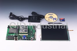
Advantech SOM-ADK2552 Design-in Kit for SOM-A2552 Intel XScale® PXA255 Processor System On Module
Part Number
SOM-ADK2552
Price
Request Quote
Manufacturer
ADVANTECH
Lead Time
Request Quote
Category
SYSTEM ON MODULE
Specifications
AMI Bus (X1 Bus)
Advantech RISC standard AMI-120 connector with driving buffers on SOM module
Audio interface
8 x 2 mm Pin header-Line-in, Line-out, MIC-in, Speaker-out, Line-in Jack and Line-out Jack
Boot loader Storage
Pre-installed on SOM module
Buzzer
Yes
Certification
FCC/CE
CRT
DB-15 connector, resolution up to 1024 x 768
Inverter
5-pin housing for LCD inverter control
LCD interface(TTL level)
40-pin Advantech standard LCD connector, 24-bit LCD interface, resolution up to 1024 x 768
LCD LVDS
20-pin Advantech standard LCD connectors, supports 1-channel LVDS signals
Operating humidity
0% ~ 90%
Operating temperature
0 ~ 60°C
OS Image Storage
Thru CompactFlash Card (CFC)
OS support
Windows CE .NET 4.2
PCMCIA/CompactFlash
1 x Type II CFC slot and 1 x Type II PCMCIA slot
Power input
12 V DC in with power switch
Serial Port
connector 2 x RS-232 DB-9 connectors (COM1, COM2); 1 x IrDA 1.1 Physical Layer (COM3); 1 x 5 x 2 2.00 mm pin header (COM4); 1 x 6 x 2 2.00 mm pin header (COM5)
SM Bus
Yes
SOM module P/N
SOM-A2552-440B0
System Backup
battery 65 mAh 2032 type rechargeable Li-ion coin battery For RTC/SDRAM
System Reset Button
H/W reset button, S/W reset button, Wakeup/Suspend button
T/S
4-wire resistive touch screen housing
TV-in
1 RCA jack for TV-in function
TV-out
1 RCA jack for TV-out function
USB Client
1 x mini USB 1.1 Client connector
USB Host
1 x USB 1.1 host connector
Watch Dog
PXA255 Built-in
Datasheet

Extracted Text
SOM-ADK2552 Series ® Design-in Kit for SOM-A2552 Intel ® Design-in Kit XScale PXA255 System On Module Introduction The Design-in Kit package provides developers a complete reference design-in suit for application evaluation/ development and their own Customer Solution Board (CSB) development. It contains all the needed information, documentation and tools for starting hands-on work with the followings items: § Target SOM (SOM-A2552-440B0): SOM-A2552 standard version board. § SOM-A2552 Series Reference Customer Solution Board: Sample CSB for developer reference. § 64 MB CompactFlash card § Design-in reference documentation: - Design-in zone login information card - Design-in Kit user’s manual - RISC SOM Carrier Board Design Guide - Schematics, bill of material, layout guide of reference CSB § Testing Set Designed for sample CSB or customers' own CSB/mass production testing. It includes: - H/W testing tools: RS232 loop-back testing tool, ADAM-4520 for RS485 testing, null MODEM cable, JTAG cable, USB ActiveSync cable, Audio cable, RS232 cable and RS485 cable. - S/W testing Utility: Advantech-developed testing utility. Testing process will be implemented by S/W testing utility and H/W testing tools. - Documentation: "Advantech RISC SOM Platform Testing Method". Users can use the base documents to know how to implement testing process. § Software Development Tools Software tools is a complete package for customers to develop their target image to align with their target CSB and applications - BSP: Binary Board Support Package for target SOM Design-in Kit. Users can integrate their target Windows CE platform into components, Apps and drivers - SDK: For customer target Application development - Reference Image: Reference Image for the selected model of SOM Design-in Kit - Upgrade Utility: Users can use the upgrade utility to upgrade boot logo, image & bootloader. - LCD Tuner: Advantech-developed program for users to tune the LCD register settings. § Design-in Zone Guide Advantech has established a dedicated website portal called SOM Design-in Zone to assist customers with CSB development by providing direct and professional technique support in most effi cient way. The home page is located at http://SOM-designin.advantech.com.tw **SOM-ADK2552-B00 does not include the LCD kit; please order your LCD kit of your choice** ARM / XScale Based Embedded Computing Solutions Online Download * Note: All specifi cations are subject to change without notice. SOM-ADK2552 Series Design-in Kit LCD Kit: (OPTIONAL item) Packing List Advantech supplies a full range of certifi ed LCD kits in difference sizes and types for § SOM-A2552-440B0 SOM-A2552 standard version board. customers to fi t into their target CSB and target application. § SOM-A2552-440B0 Carrier board for SOM-A2552-440B0 Each LCD kit includes the selected LCD panel, inverter and needed cables which carrier board are designed to work with each Advantech Standard RISC-based SOM Design-in Kit § 64MB compact fl ash card platform. § Testing Kit Includes H/W testing tools, S/W testing utility and The current available LCD kits include the following: documentation. § 6.4" TFT VGA LCD kit (PRIMEVIEW/PD064VT2) § AC power Adaptor AC/DC power adaptor for Design-in kit power supply. § 10.4" TFT SVGA LCD kit (AU/ UB104SXX) § SOM-A2552 series Includes Software Development tools, SOM-A2552 § 15" TFT XGA LCD kit (AUO/ M150XN07) support CD specs, SOM-ADK2552 specs, SOM-A2552 manual, SOM-ADK2552 manual, Testing Kit application note & SOM-A2552 carrier board design guide. Specifi cations § PCB Form factor 237 mm x 160 mm Ordering Information § SOM module P/N SOM-A2552-440B0 § Boot loader Storage Pre-installed on SOM module SOM-A2552 Design-in Package § OS Image Storage Thru CompactFlash Card (CFC) § Design-in Kit SOM-A2552 Series Design-in Kit. (** without Panel) § AMI Bus (X1 Bus) Advantech RISC standard AMI-120 connector with SOM-ADK2552-B00 driving buffers on SOM module (Must order) § Watch Dog PXA255 Built-in § LCD Kit 6.4" TFT VGA LCD kit. The kit includes 4-wire LCD-A064-TTV1-0 resistive T/S, inverter, cables and installation guide. § RTC External RTC w/backup power pin (Optional item) § System Backup battery 65 mAh 2032 type rechargeable Li-ion coin battery For RTC/SDRAM § LCD Kit 10.4" TFT SVGA LCD kit. The kit includes 4-wire LCD-A104-TTS1-0 resistive T/S, inverter, cables and installation guide. § Serial Port connector 2 x RS-232 DB-9 connectors (COM1,COM2) (Optional item) 1 x IrDA 1.1 Physical Layer (COM3) 1 x 5 x 2 2.00 mm pin header (COM4) § LCD-A150-TTX2-0 15” TFT XGA kit. This kit includes 4-wire resistive T/S, inverter, cables and installation guide.. 1 x 6 x 2 2.00 mm pin header (COM5) (Optional item) § PCMCIA/CompactFlash 1 x Type II CFC slot and 1 x Type II PCMCIA slot § RISC Windows CE Builder RISC CE-Builder Windows CE .Net 4.2 version 1. § USB Host 1 x USB 1.1 host connector RSW-ACEBW1-042 § USB Client 1 x mini USB 1.1 Client connector (Optional item) § LCD interface 40-pin Advantech standard LCD connector, 24-bit (TTL level) LCD interface, resolution up to 1024 x 768 § LCD LVDS 20-pin Advantech standard LCD connectors, supports 1-channel LVDS signals § CRT DB-15 connector, resolution up to 1024 x 768 § TV-in 1 RCA jack for TV-in function § TV-out 1 RCA jack for TV-out function § T/S 4-wire resistive touch screen housing § Audio interface 8 x 2 mm Pin header-Line-in, Line-out MIC-in, Speaker-out, Line-in Jack and Line-out Jack § Buzzer Yes § SM Bus Yes § System Reset button H/W reset button, S/W reset button, Wakeup/Suspend button § OS support Windows CE .NET 4.2 § Power input 12 V DC in with power switch § Inverter 5-pin housing for LCD inverter control § Operating temperature 0 ~ 60° C § Operating humidity 0% ~ 90% § Certifi cation FCC/CE ARM / XScale Based Embedded Computing Solutions Online Download www.advantech.com/products
Frequently asked questions
Why do business with Advantech Boards?

Will there be a warranty for the SOM-ADK2552?
Which companies are available as carriers?
I don't live in the USA. Will Advantech Boards work with me?
Will Advantech Boards accept my preferred method of payment?
Why buy from GID?

Quality
We are industry veterans who take pride in our work

Protection
Avoid the dangers of risky trading in the gray market

Access
Our network of suppliers is ready and at your disposal

Savings
Maintain legacy systems to prevent costly downtime

Speed
Time is of the essence, and we are respectful of yours
Related Products

Advantech SOM-2353P-GDA1 AMD SOM-144 Module w/GX1-300, 64MB RAM, VGA/LCD & Audio

Advantech SOM-144 Module w/CPU, VGA/LCD & LAN w/on-board AMD GX533-400 MHz CPU

ADVANTECH SOM-2365L-LDB1 Transmeta SOM-144 Module w/CPU, 64MB RAM, Audio, SSD & LAN
Advantech SOM-2365N-LDB1 CPU Board with SOM-144 PCI with TM5400-500 /64MB/LAN Rev.B1

Advantech SOM-2366L-QEA1 Transmeta SOM-144 Module w/TM5800-800 CPU
Request a Quote

The quote request has been received
Close

Facing challenges or have inquiries? Feel free to contact us!
Call Us +1-469-283-2440
What they say about us
FANTASTIC RESOURCE
One of our top priorities is maintaining our business with precision, and we are constantly looking for affiliates that can help us achieve our goal. With the aid of GID Industrial, our obsolete product management has never been more efficient. They have been a great resource to our company, and have quickly become a go-to supplier on our list!
Bucher Emhart Glass
EXCELLENT SERVICE
With our strict fundamentals and high expectations, we were surprised when we came across GID Industrial and their competitive pricing. When we approached them with our issue, they were incredibly confident in being able to provide us with a seamless solution at the best price for us. GID Industrial quickly understood our needs and provided us with excellent service, as well as fully tested product to ensure what we received would be the right fit for our company.
Fuji
HARD TO FIND A BETTER PROVIDER
Our company provides services to aid in the manufacture of technological products, such as semiconductors and flat panel displays, and often searching for distributors of obsolete product we require can waste time and money. Finding GID Industrial proved to be a great asset to our company, with cost effective solutions and superior knowledge on all of their materials, it’d be hard to find a better provider of obsolete or hard to find products.
Applied Materials
CONSISTENTLY DELIVERS QUALITY SOLUTIONS
Over the years, the equipment used in our company becomes discontinued, but they’re still of great use to us and our customers. Once these products are no longer available through the manufacturer, finding a reliable, quick supplier is a necessity, and luckily for us, GID Industrial has provided the most trustworthy, quality solutions to our obsolete component needs.
Nidec Vamco
TERRIFIC RESOURCE
This company has been a terrific help to us (I work for Trican Well Service) in sourcing the Micron Ram Memory we needed for our Siemens computers. Great service! And great pricing! I know when the product is shipping and when it will arrive, all the way through the ordering process.
Trican Well Service
GO TO SOURCE
When I can't find an obsolete part, I first call GID and they'll come up with my parts every time. Great customer service and follow up as well. Scott emails me from time to time to touch base and see if we're having trouble finding something.....which is often with our 25 yr old equipment.
ConAgra Foods